Jeep Parts Wiki | Ford Parts Wiki
Home | Search | Browse
Prev
 Next
Next
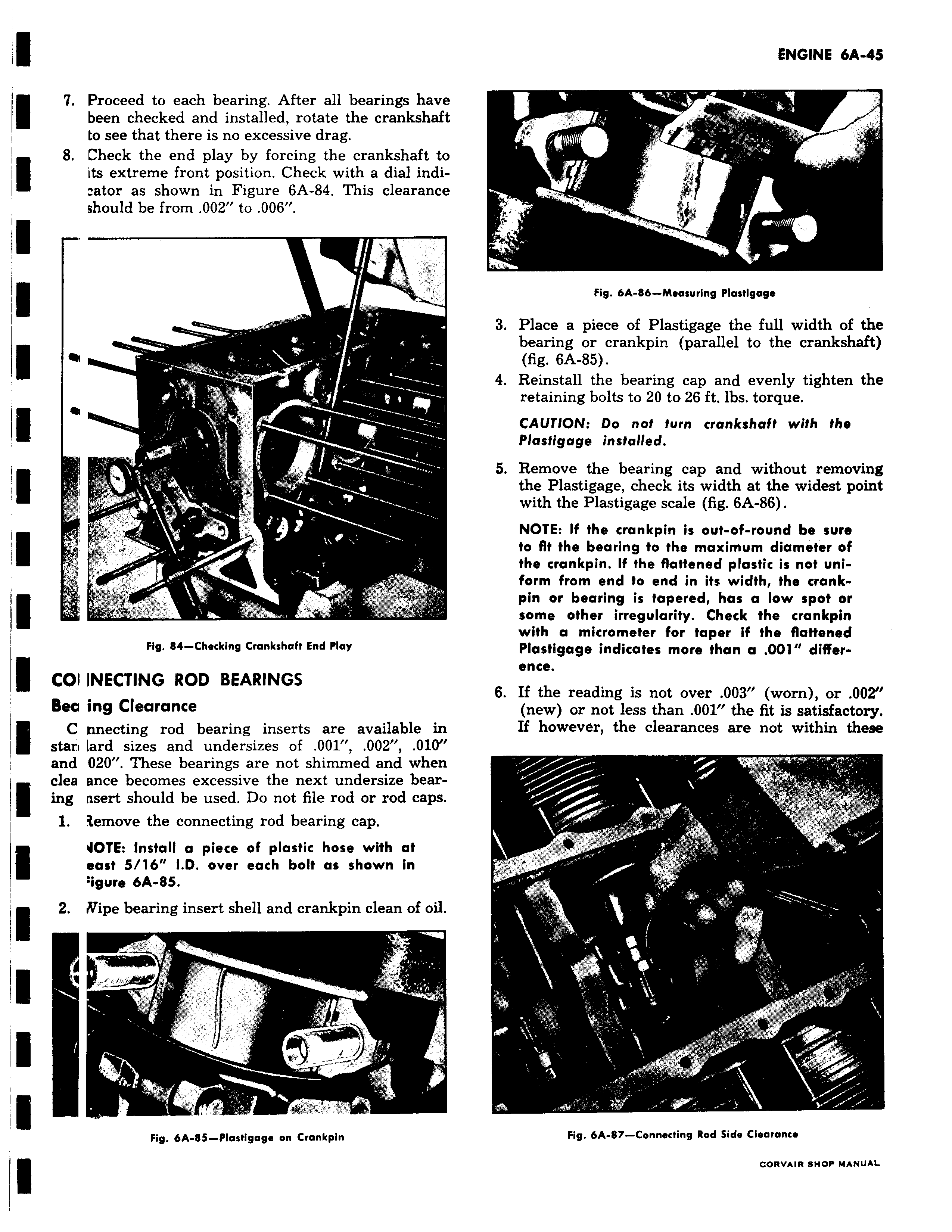
7 Proceed to each bearing After all bearings have been checked and installed rotate the crankshaft to see that there is no excessive drag 8 Check the end play by forcing the crankshaft to its extreme front position Check with a dial indi ator as shown in Figure 6A 84 This clearance should be from 002 to 006 y e e a r r Fig 84 Checking Crankshaft End Play COI INECTING ROD BEARINGS Bee ing Clearance C nnecting rod bearing inserts are available in stan lard sizes and undersizes of 001 002 010 and 020 These bearings are not shimmed and when clea ance becomes excessive the next undersize bear ing nsert should be used Do not file rod or rod caps 1 3emove the connecting rod bearing cap 4OTE Install a piece of plastic hose with at east 5 16 LD over each bolt as shown in igure 6A 85 2 Wipe bearing insert shell and crankpin clean of oil Fig 6A 85 Plastigage on Crankpin r r 41 Fig 6A Bb Measuring Plastigage 3 Place a piece of Plastigage the full width of the bearing or crankpin parallel to the crankshaft fig 6A 85 4 Reinstall the bearing cap and evenly tighten the retaining bolts to 20 to 26 ft lbs torque CAUTION Do not turn crankshaft with the Plastigage installed 5 Remove the bearing cap and without removing the Plastigage check its width at the widest point with the Plastigage scale fig 6A 86 NOTE If the crankpin is out of round be sure to fit the bearing to the maximum diameter of the crankpin If the flattened plastic is not uniform from end to end in its width the crankpin or bearing is tapered has a low spot or some other irregularity Check the crankpin with a micrometer for taper if the flattened Plastigage indicates more than a 001 difference 6 If the reading is not over 003 worn or 002 new or not less than 001 the fit is satisfactory If however the clearances are not within these T Tt t r C It r Fig 6A 87 Connecting Rod Side Clearance