Jeep Parts Wiki | Ford Parts Wiki
Home | Search | Browse
Prev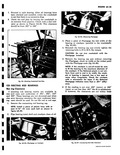
 Next
Next
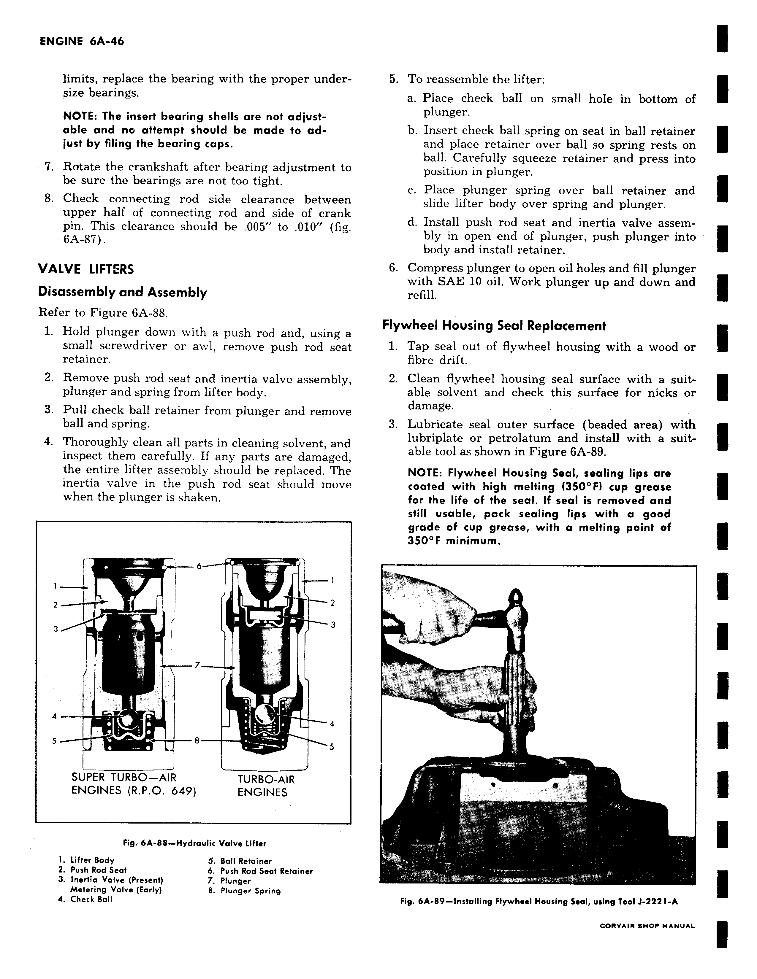
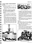
limits replace the bearing with the proper undersize bearings NOTE The insert bearing shells are not adjustable and no attempt should be made to adjust by filing the bearing caps 7 Rotate the crankshaft after bearing adjustment to be sure the bearings are not too tight 8 Check connecting rod side clearance between upper half of connecting rod and side of crank pin This clearance should be 005 to 010 fig 6A 87 VALVE LIFTERS Disassembly and Assembly Refer to Figure 6A 88 1 Hold plunger down with a push rod and using a small screwdriver or awl remove push rod seat retainer 2 Remove push rod seat and inertia valve assembly plunger and spring from lifter body 3 Pull check ball retainer from plunger and remove ball and spring 4 Thoroughly clean all parts in cleaning solvent and inspect them carefully If any parts are damaged the entire lifter assembly should be replaced The inertia valve in the push rod seat should move when the plunger is shaken a I 1 2 I 2 3 i 4 4 5 8 5 SUPER TURBO AIR TURBO AIR ENGINES R P O 649 ENGINES Fig 6A 88 Hydraulic Valve Lifter 1 Lifter Body 5 Ball Retainer 2 Push Rod Seat 6 Push Rod Seat Retainer 3 Inertia Valve Present 7 Plunger Metering Valve Early 8 Plunger Spring 4 Check Ball 5 To reassemble the lifter a Place check ball on small hole in bottom of plunger b Insert check ball spring on seat in ball retainer and place retainer over ball so spring rests on ball Carefully squeeze retainer and press into position in plunger c Place plunger spring over ball retainer and slide lifter body over spring and plunger d Install push rod seat and inertia valve assembly in open end of plunger push plunger into body and install retainer 6 Compress plunger to open oil holes and fill plunger with SAE 10 oil Work plunger up and down and refill Flywheel Housing Seal Replacement 1 Tap seal out of flywheel housing with a wood or fibre drift 2 Clean flywheel housing seal surface with a suitable solvent and check this surface for nicks or damage 3 Lubricate seal outer surface beaded area with lubriplate or petrolatum and install with a suitable tool as shown in Figure 6A 89 NOTE Flywheel Housing Seal sealing lips are coated with high melting 350 F cup grease for the life of the seal If seal is removed and still usable pack sealing lips with a good grade of cup grease with a melting point of 350 F minimum i 7 Fig 6A 89 installing Flywheel Housing Seal using Tool J 2221 A