Jeep Parts Wiki | Ford Parts Wiki
Home | Search | Browse
Prev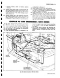
 Next
Next
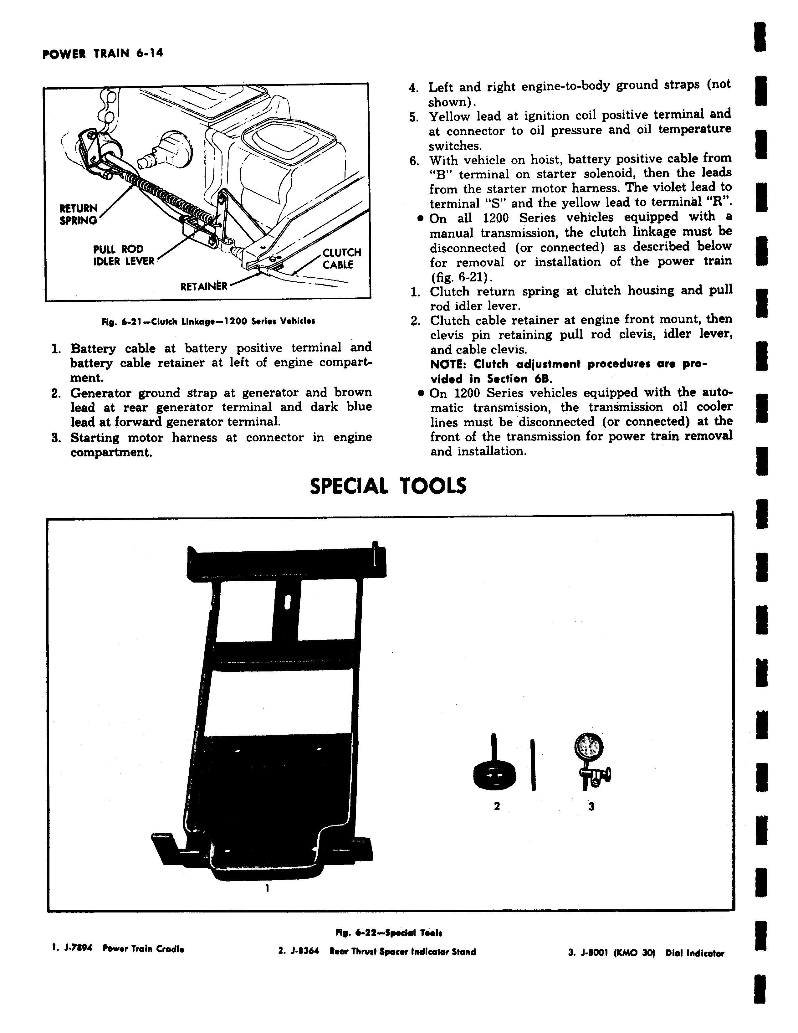
A s 1 CrCr l 1 4 Left and right engine to body ground straps not shown 5 Yellow lead at ignition coil positive terminal and at connector to oil pressure and oil temperature switches 6 With vehicle on hoist battery positive cable from B terminal on starter solenoid then the leads from the starter motor harness The violet lead to terminal S and the yellow lead to terminal R e On all 1200 Series vehicles equipped with a manual transmission the clutch linkage must be disconnected or connected as described below for removal or installation of the power train fig 6 21 1 Clutch return spring at clutch housing and pull rod idler lever 2 Clutch cable retainer at engine front mount then clevis pin retaining pull rod clevis idler lever and cable clevis NOTE Clutch adjustment procedures are provided in Section 6B e On 1200 Series vehicles equipped with the automatic transmission the transmission oil cooler lines must be disconnected or connected at the front of the transmission for power train removal and installation L TOOLS Z 3 Special Tools lpacerlndicator Stand 3 J 8001 Kh10 30 Dial indicator