Jeep Parts Wiki | Ford Parts Wiki
Home | Search | Browse
Prev
 Next
Next
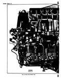
SECT POWEI CONTENTS C Cor tir 500 700 and 900 Series Cori tir 95 and Greenbrier 1200 Series Ir Page Gew ral Description 6 1 Serv ee Operations 6 4 In roduction 6 4 R moval of Power Train from Vehicle 6 4 Si aration of Power Train Major Components 6 7 Chree or Four Speed Transaxle 6 7 Removal of Transaxle from Engine 6 7 Separation of Three or Four Speed Transmission from Differential Carrier 6 7 Repair Procedures 6 7 Automatic Powerglide Transaxle 6 7 Removal of Transaxle from Engine 6 7 Separation of Automatic Transmission from Differential Carrier 6 8 Repair Procedures 6 8 GENERAL T te 1961 Corvair passenger car power train fig 6 1 inc rporates the following design revisions which shu Jd be noted relative to its removal and installa tiol from the vehicle l 0 Engine rear mount now shear type 0 Revised fuel induction system incorporating manual choke n Optional Perimeter heater which utilizes engine heat for passenger compartment Ze Corvair power train consists of a horizontallyop i sed air cooled six cylinder engine integrated with a I ansaxle to form a compact unit fig 6 1 he standard driveline is a manual shift three speed tra smission coupled with a 3 27 1 rear axle Optional tra smissions include a four speed transmission and an automatic transmission 3 55 1 ratio rear axle is av lable with any of the transmissions s illustrated the transmission is separated from the enj ne by the differential carrier rear axle In relatioi to their installed positions the transmission is toN ard the front of the vehicle and the engine is at If the rear racing the power flow engine torque is transmitted ION 6 It TRA1 N IF THIS SECTION Page 6 1 6 13 JDEX Page Powerglide Selective Thrust Washer Determination 6 8 Assembly of Power Train Major Components 6 9 Three or Four Speed Transaxle 6 9 Assembly of Three or Four Speed Transmission and Differential Carrier 6 9 Assembly of Three or Four Speed Transaxle to Engine 6 9 Automatic Powerglide Transaxle 6 10 Assembly of Automatic Transmission and Differential Carrier Includes Rear Selective Thrust Washer Determination 6 10 Assembly of Automatic Transaxle to Engine 6 11 Installation of Power Train in Vehicle 6 12 Special Tools 6 13 DESCRIPTION to the transmission by means of a shaft from the clutch which runs axially through the pinion shaft The torque is then multiplied in the transmission or passed on in the same ratio to the rear axle pinion which is splined to the transmission shaft From this point the power flow is conventional as the pinion drives a ring gear bolted to a differential which drives the axle shafts through its side gears An essentially alike power flow results with the optional automatic transmission version the major exceptions being that a torque converter is mounted at the clutch location and two shafts run from the converter to the Powerglide unit Considering the turbine shaft as functionally comparable to the clutch shaft except that it is hollow the second shaft is necessary to drive the front pump of the automatic transmission A three point mounting is used with the power train Two mounts attached to the transmission support the front of the unit at the rear suspension cross member and the third mount is located at the rear center of the engine and attaches to the integrated bodyframe Descriptions of the individual power train components are provided in Sections 6A through 6E vuR SHOP MANUAL