Jeep Parts Wiki | Ford Parts Wiki
Home | Search | Browse
Prev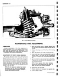
 Next
Next
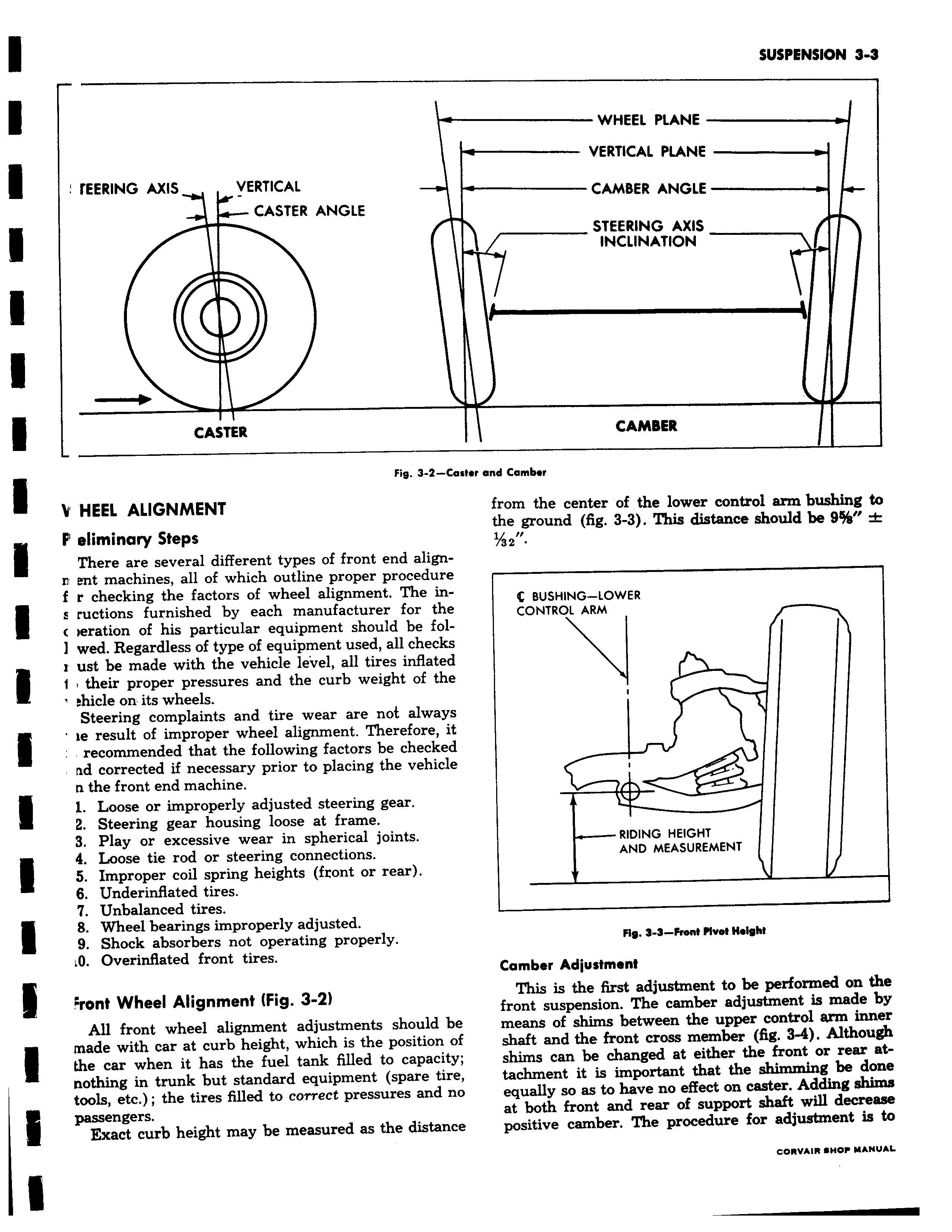
fEERING AXIS VERTICAL CASTER ANGLE CASTER Fig 3 2 C V HEEL ALIGNMENT P eliminary Steps There are several different types of front end alignn ent machines all of which outline proper procedure f r checking the factors of wheel alignment The in s ructions furnished by each manufacturer for the c eration of his particular equipment should be fol wed Regardless of type of equipment used all checks r ust be made with the vehicle level all tires inflated 1 their proper pressures and the curb weight of the hicle on its wheels Steering complaints and tire wear are not always te result of improper wheel alignment Therefore it recommended that the following factors be checked ad corrected if necessary prior to placing the vehicle n the front end machine 1 Loose or improperly adjusted steering gear 2 Steering gear housing loose at frame 3 Play or excessive wear in spherical joints 4 Loose tie rod or steering connections 5 Improper coil spring heights front or rear 6 Underinflated tires 7 Unbalanced tires 8 Wheel bearings improperly adjusted 9 Shock absorbers not operating properly A Overinflated front tires Front Wheel Alignment Fig 3 2 All front wheel alignment adjustments should be made with car at curb height which is the position oi the car when it has the fuel tank filled to capacity nothing in trunk but standard equipment spare tire tools etc the tires filled to correct pressures and nc passengers Exact curb height may be measured as the distancE WHEEL PLANE VERTICAL PLANE CAMBER ANGLE STEERING AXIS INCLINATION CAMBER aster and Camber from the center of the lower control arm bushing to the ground fig 3 3 This distance should be 9 t 1 a 2 BUSHING LOWER CONTROL ARM T I RIDING HEIGHT AND MEASUREMENT Fig 9 9 Front Rvet Height Camber Adjustment This is the first adjustment to be performed on the front suspension The camber adjustment is made by means of shims between the upper control arm inner shaft and the front cross member fig 3 4 Although shims can be changed at either the front or rear at tachment it is important that the shimming be done equally so as to have no effect on caster Adding shims at both front and rear of support shaft will decrease positive camber The procedure for adjustment is to CORVAIR SHOP MANUAL