Jeep Parts Wiki | Ford Parts Wiki
Home | Search | Browse
Prev
 Next
Next
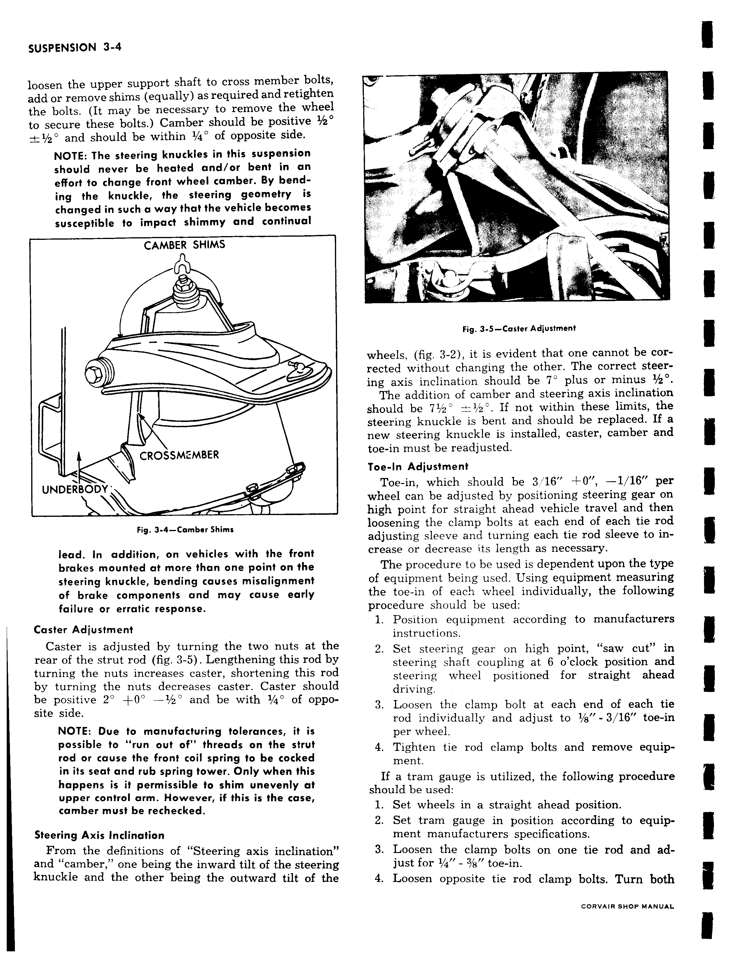
loosen the upper support shaft to cross member bolts add or remove shims equally as required and retighten the bolts It may be necessary to remove the wheel to secure these bolts Camber should be positive z 1 2 and should be within 1 4 of opposite side NOTE The steering knuckles in this suspension should never be heated and or bent in an effort to change front wheel camber By bending the knuckle the steering geometry is changed in such a way that the vehicle becomes susceptible to impact shimmy and continual CAMBER SHIMS CROSSME EMBER UNDERBOD Fig 3 4 Camber Shims lead In addition on vehicles with the front brakes mounted at more than one point on the steering knuckle bending causes misalignment of brake components and may cause early failure or erratic response Caster Adjustment Caster is adjusted by turning the two nuts at the rear of the strut rod fig 3 5 Lengthening this rod by turning the nuts increases caster shortening this rod by turning the nuts decreases caster Caster should be positive 2 0 1 z and be with 1 4 of opposite side NOTE Due to manufacturing tolerances it is possible to run out of threads on the strut rod or cause the front coil spring to be cocked in its seat and rub spring tower Only when this happens is it permissible to shim unevenly at upper control arm However if this is the case camber must be rechecked Steering Axis Inclination From the definitions of Steering axis inclination and camber one being the inward tilt of the steering knuckle and the other being the outward tilt of the AP ilk I Ad Fig 3 5 Caster Adjustment wheels fig 3 2 it is evident that one cannot be corrected without changing the other The correct steering axis inclination should be 7 plus or minus 1 20 The addition of camber and steering axis inclination should be 71 2 1 2 If not within these limits the steering knuckle is bent and should be replaced If a new steering knuckle is installed caster camber and toe in must be readjusted Toe In Adjustment Toe in which should be 3 16 I O 1 16 per wheel can be adjusted by positioning steering gear on high point for straight ahead vehicle travel and then loosening the clamp bolts at each end of each tie rod adjusting sleeve and turning each tie rod sleeve to increase or decrease its length as necessary The procedure to be used is dependent upon the type of equipment being used Using equipment measuring the toe in of each wheel individually the following procedure should be used 1 Position equipment according to manufacturers instructions 2 Set steering gear on high point saw cut in steering shaft coupling at 6 o clock position and steering wheel positioned for straight ahead driving 3 Loosen the clamp bolt at each end of each tie rod individually and adjust to 1 s 3 16 toe in per wheel 4 Tighten tie rod clamp bolts and remove equipment If a tram gauge is utilized the following procedure should be used 1 Set wheels in a straight ahead position 2 Set tram gauge in position according to equipment manufacturers specifications 3 Loosen the clamp bolts on one tie rod and adjust for 1 4 3 8 toe in 4 Loosen opposite tie rod clamp bolts Turn both GORVAIR SHOP MANUAL