Jeep Parts Wiki | Ford Parts Wiki
Home | Search | Browse
|
Corvair Chassis Shop Manual December 1964 |
|
Prev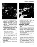

 Next
Next
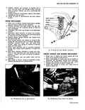
Fig 75 Shock Absorber Upper Attachment Location and cam then pull strut rod out of bracket and remove bushing caps 5 Place strut rod and bracket assembly in a vise and remove strut rod to bracket through bolt Separat bracket and strut rod then remove bushing caps from strut rod 6 Install bushing caps to inboard end of strut rod and position rod to bracket Install pivot bolt washer and nut tighten nut but do not torque at this time l v STRUT ROD I TO AXLE i BRACKET PIVOT BOLT WN CAMBER REAR STRUT ROD ADJUSTMENT CAM BOLT CAM BUSHING CAPS Fig 76 Rear Strut Rod Attachment 7 Insijall bushing caps to outboard end of strut rod and posItion rod to bracket at torque arm Install cam bolt and cam Install cam bolt nut and tighten but do ot torque at this time 8 Witii spring compressed as in Step 1 position strut bracket to differential carrier Install bracket todifferential carrier bolts and torque to specifications To prevent distortion to strut bracket it is recommended that the retaining bolts be installed in the following manner a Using a long drift align bracket with differential carrier and install the forward bolt on the side of Earrier Do not tighten bolt Installation of re maining bolts will require further alignment b Align bracket with rear bolt on underside of carrier using drift to align bracket during bolt installation c Install rear bolt an side of carrier then install remaining bolt to underside of carrier d Alternately tighten all bolts in small increment to permit an even draw against bracket Tighten k11 bolts snugly and check bracket for proper seating against carrier Torque all bolts to Opecifications 9 Alitn camber cam with reference mark on torque arna bracket and tighten nut to retain setting If strut rod has been replaced camber setting should be checked 10 Remove support from torque arm install wheel and tire assembly lower vehicle so that weight rest on wheliels and torque strut rod and wheel nuts FRONT STRUT ROD AND BRACKET REPLACEMENT 1 Raise vehicle sufficiently to permit access to front strut rod bracket at transmission support 2 Disconnect strut rod bracket at transmission support by removing the retaining nuts fig 77 3 Remove nut retainer and grommet securing strut rod to torque arm 4 Remove strut rod and bracket assembly from torque arm and clamp bracket in vise Remove nut retainer and grommet securing strut rod to bracket 5 Position retainer and grommet against shoulder on strut rod then place strut rod in bracket Install gro nmet retainer and nut to retain strut rod to bracket TORQUE ARM TO UNDER60DY BRACKET TOE IN ADJUSTMENT FRONT STRUT ROD TORQUE CONTROL ARM FRONT STRUT ROD TO TRANSMISSION SUPPORT BRACKET Fig 77 Front Strut Rod Attachment