Jeep Parts Wiki | Ford Parts Wiki
Home | Search | Browse | Marketplace | Messages | FAQ | Guest
|
Corvair Chassis Shop Manual December 1964 |
|
Prev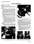
 Next
Next
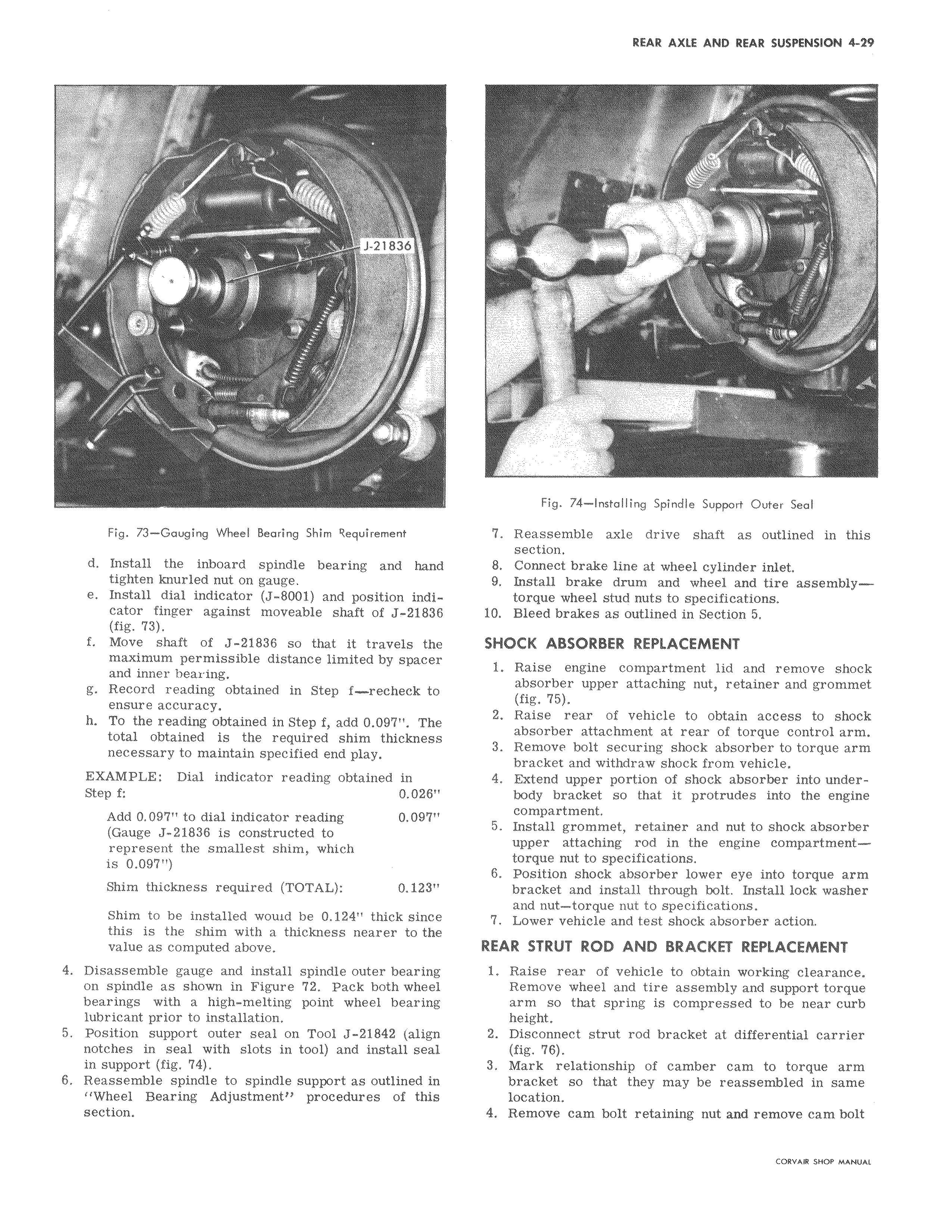
l y T J 21836 c r Fig 73 Gauging Wheel Bearing Shim Requirement d Install the inboard spindle bearing and hand tighten knurled nut on gauge e Install dial indicator J 8001 and position indicator finger against moveable shaft of J 21836 fig 73 f Move shaft of J 21836 so that it travels the maximum permissible distance limited by spacer and inner bearing g Record reading obtained in Step f recheck to ensure accuracy h To the reading obtained in Step f add 0 097 The total obtained is the required shim thickness necessary to maintain specified end play EXAMPLE Dial indicator reading obtained in Step f 0 028 Add 0 097 to dial indicator reading 0 097 Gauge J 21836 is constructed to represent the smallest shim which is 0 097 Shim thickness required TOTAL 0 123 Shim to be installed wouid be 0 124 thick since this is the shim with a thickness nearer to the value as computed above 4 Disassemble gauge and install spindle outer bearing on spindle as shown in Figure 72 Pack both wheel bearings with a high melting point wheel bearing lubricant prior to installation 5 Position support outer seal on Tool J 21842 align notches in seal with slots in tool and install seal in support fig 74 6 Reassemble spindle to spindle support as outlined in Wheel Bearing Adjustment procedures of this section i yr r F i w i Fig 74 installing Spindle Support Outer Seal 7 Reassemble axle drive shaft as outlined in this section 8 Connect brake line at wheel cylinder inlet 9 Install brake drum and wheel and tire assemblytorque wheel stud nuts to specifications 10 Bleed brakes as outlined in Section 5 SHOCK ABSORBER REPLACEMENT 1 Raise engine compartment lid and remove shock absorber upper attaching nut retainer and grommet fig 75 2 Raise rear of vehicle to obtain access to shock absorber attachment at rear of torque control arm 3 Remove bolt securing shock absorber to torque arm bracket and withdraw shock from vehicle 4 Extend upper portion of shock absorber into underbody bracket so that it protrudes into the engine compartment 5 Install grommet retainer and nut to shock absorber upper attaching rod in the engine compartmenttorque nut to specifications 6 Position shock absorber lower eye into torque arm bracket and install through bolt Install lock washer and nut torque nut to specifications 7 Lower vehicle and test shock absorber action REAR STRUT ROD AND BRACKET REPLACEMENT 1 Raise rear of vehicle to obtain working clearance Remove wheel and tire assembly and support torque arm so that spring is compressed to be near curb height 2 Disconnect strut rod bracket at differential carrier fig 76 3 Mark relationship of camber cam to torque arm bracket so that they may be reassembled in same location 4 Remove cam bolt retaining nut and remove cam bolt CORVAIR SHOP MANUAL