| Book |
Page |
Context |
 |
 |
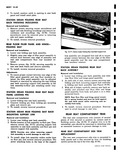
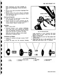
beaded area with lubriplate or petrolatum and install with a suitable tool as shown in Figure 6A 76 NOTE Seal i coated with a high melting 350 11 point cup grease between sealing lips ...
inside diameter as shown in Figure 6A 76 Seal to be installed must have this cup grease which is maintained for the life of the seal Housing Replacement When replacing the engine rear housing ...
outlined e Install distributor holding stud 1 measured from distributor pad on engine rear housing fig 6A 76 SEALING LIPS Fig 6A 76 imfollinq Roar Housing Seal Using Tool |
|
 |
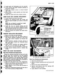
screws securing corner escutcheons and upper and side finishing mouldings and remove escutcheons and mouldings fig 10 76 Corner escutcheons must be removed prior to removing side and upper moldings 2 To install reverse removal ...
rear edge of assembly and rear seat compartment floor rear insulator retainer 3 Remove screws fig 10 76 securing assembly to rear seat back frame and remove assembly 4 To install reverse removal procedure Adjustments ...
securing rear folding seat back mounting support link assembly to folding seat back assembly see Figure 10 76 3 With aid of helper carefully remove seat back assembly and attached rear floor filler and hinge |
|
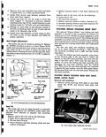 |
CATCH PLATE Removal and Installation 1 Remove screws securing catch plate to seat back panel fig 10 76 and remove catch plate and catch FINISHING MOULDING AND ESCUTCHEONS SCREWS w FILLER PANEL Fig 10 76 |
|
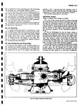 |
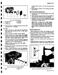
which is driven by the end of the distributor shaft A spring loaded pressure regulator fig 6A 76 located in the engine rear housing regulates the maximum pressure of the lubrication system |
|
 |
shown in Figure 10 52a i x 3 I y f sy s l y CEMENT 76 TRIM WEATHERSTRIP AS SHOWN BUTT ENDS CEMENT TOGETHER TUBULAR SECTION MUST BE OPEN TO PROVIDE |
|
 |
with high melting cup grease for the life of the seal 350 F Refer to Figure 6A 76 for a cross section of seal 1 Install seal over crankshaft and tap in place with |
|
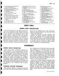 |
Inner Front 88 Reinforcement 75 Panel Rocker Inner Center At Kick Up Sic 89 Cover Rear Se 76 Panel Rocker Inner Rear Heater Openini BODI GENERAL BOD The body design used on the 1961 Chevrolet |
|
 |
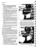
pump outlet connection 2 Install the pump into the accessory housinE 2 3 4 Fig 9 76 Pus l Cover 3 Diaphragm and Body Assembly 2 Spring 4 Lower Body 1 i RETURN SPRING PUMP |
|
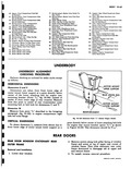 |
Inner Front Kick UP Reinforcement 74 Panel Rocker Inner Center ck Up Cenf 91 Broce Reor W 76 Panel Rocker Inner Rear Mounting Supp UNDI UNDERBODY ALIGNMENT CHECKING PROCEDURE Perform checking as outlined for sedan |
|
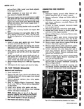 |
Remove pressure regulator plug nylon gasket spring and valve 4 Refer to Repairs Engine Components Figure 6A 76 under Off the Vehicle Service Operations in this section 5 Install valve spring nylon gasket and plug |
|
 |
76 |