| Book |
Page |
Context |
 |
 |
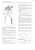
UOVPY install new cover at room temperature approxi at back window opening mately 72 F NOTE Drive DHHS ml best D9 l m V d DY NOTE Where new cover is installed at tem first ...
driving a screwdriver or suitable tool under pgpgtuygs bglgw 72 F pllg S f brje led as shown the heads of the nails to loosen them Diagonal in Figure 2 7 will gid in removing |
 |
 |
cover at YOOITL temperature approxi Op umg at each Sgam UCnti n View iA Fig mately 72 F g 3 NOTE When new COVQF installed at tem f Carefully smooth out cover to each side ...
roof weratures below 72 F pliers fabricated is shown f rail and attach cover cement only Check tit of in Figure 2Jl will aid in removing wrinkles www 3 Determine center line of roof panel |
 |
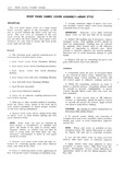 |
lusmlled at tem Diagonal cutters or similar tool can then be pEl 3 tm S below 72 7 pliers fablwcat d as Shown used to grasp iiaiis wid twist iiism out Un in Figure |
 |
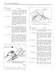 |
front center of slot of side rail I metal See 5A4 REFERENCE POINT DIRECTLY Q 72 Body front tie down slot use BELOW CENTER OF BOLT front center of slot of side rail |
 |
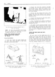 |
Paint fihu put a 1 4 wide by 3 B deep slot in a J 2 I 72 headlining inserting tool or equivalent FRONT AND REAR DOOR ARM RESTS A YL FRONT DOOR WINDOW GLASS |
 |
 |
Bucket Seat Manual 2H8 I Iandle Door Outside 2DG C Handle Door Inside 21 72 Headlining 2G Catch Clips Folding Top 2138 Hinge Door Front 2DlO Cleaning Trim IA Hinge Rear Compartment 2F8 Clips Catch |
 |
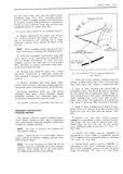 |
Cement nun may type I nbbnr Spacers lation method should be used only in conjunction 43934 72 or equivalent to upper windshield pinch with an installation requiring complete replacement Weld fjnngey One each sing |
 |
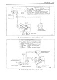 |
FEEDrREARWARD UP CYCLE L ZI LIGHT GREEN SOLENOIDVVERTICAL MOVEMENT 22 TAN BLANK IA LIGHT BLUE SOLENOIDJIORIZONTAL MOVEMENT 72 24 nw TRAN5M S ON ClUTCH 42 LYMFI CONTROL SOLENOIDS m cancun I LLLIL BREAKER 20 SEAT |
 |
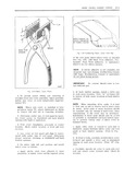 |
first use an awl or similar tool to start a hole peratures below 72 pliers fabricated as shown in in tFi1 Drive imiis at sgmii iocatimis Sh uid in FMUTE U2 will am in renmving |
 |
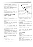 |
attaching bolts and bolt located on door hinge pillar arrow B remove stop Fig 1DG5 Fig lD 72 4 Remove front guide support bracket attaching 3 On 45 46000 series remove glass run chan bolt |
 |
 |
72 |
 |
 |
72 |
 |
 |
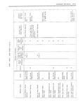
GENERAL INFORMATION 5A 5 Fig Fig Ref Dimension Location Ref Dimension Location Q 72 Cont metal See Fig BA4 and 3 4 rail and motor compartment rear master gauge hole i11 motor com cross rail |


