| Book |
Page |
Context |
 |
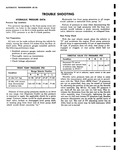 |
Range Selector Position R N D L At idle 16 Hg 81 98 47 57 47 57 71 82 At idle with vacuum hose disconnected 140 157 71 82 71 82 71 82 at balance |
|
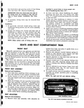 |
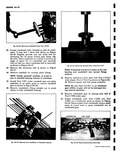
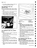
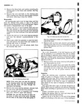
balance spring attached to seat adjuster front support and seat bottom frame as shown in Figure 10 71 3 Operate adjusters so that both front and rear attaching bolts are accessible 4 Squeeze hooked ...
locking wire from adjuster 5 Remove adjuster to seat bottom frame front and rear attaching bolts fig 71 and remove seat adjuster from seat assembly 6 To install reverse removal procedure Check seat assembly ...
SEAT DIUSTER COUNTERBALANCE SPRING ATTACHING L KIN I BOLTS RETAINERS i WIRE TENSIONAL HOLES Fig 10 71 Seat Adjusters Assembled to Front Seat |
|
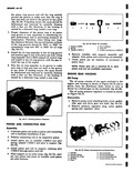 |
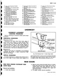
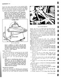
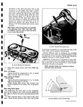
should be 0012 to 0032 for compression rings and 002 to 0035 for oil rings fig 6A 71 8 Install the oil ring expander in the oil ring groove and position gap in line with ...
However if the binding is caused by a distorted ring install a new ring r Fig 6A 71 Checking Groove Clearance PISTON AND CONNECTING ROD Assembly 1 Lubricate piston pin holes in piston and connecting |
|
 |
pfft s 111AWRY yY A t k Y7 l 4 11 I y r r y w 71 |
|
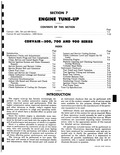 |
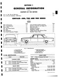
ENGINE CONTENTS OF Corvair 500 700 and 900 Series Corvair 95 and Greenbrier 1200 Series CORVAIR 500 71 n Page Introduction 7 1 Mechanical Checks and Adjustments 7 2 Remove Spark Plugs and Test Compression |
|
 |
serviced as outlined for 500 700 and 900 vehicles except that desired reading should be 71 4 for 1200 series vehicles Tee in Adjustment Follow instructions for toe4n adjustment on Corvair |
|
 |
71 |
|
 |
reverse the above removal procedure LOCK Y REMOTE LOCK CONTROL ACTUATING ARM ARM SPRING WASHER Fig 10 71 a Removing Remote Control Arm SIDE INTERMEDIATE DOOR LOCK ASSEMBLY Removal 1 Remove trim panel on models |
|
 |
Floor Pon 87 Retainer Rear 70 Support Rocker To Pillar Hose Connector Mounting Nut 71 Connector Rocker To Pillar Hose Inner 88 Reinforcement 72 Connector Rocker To Pillar Hose Outer At Kick |
|
 |
lower rear edge of seat back trim from front seat cushion spring assembly see Figure 10 71 3 Raise trim and remove cardboard breakover foundation to expose seat cushion spring attachment to seat back frame |
|
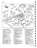 |
71 72 28 54 56S 1e 55 58 59 03 53 80 61 57 4j Fig 10 3 Exploded View of Underh 1 Support Heat Exchanger Bolt 22 Extension Heat 2 Cover Heat Exchanger Opening |
|
 |
Floor f an 84 Extension Fron 70 Support Rocker To Pillar Hose Connector Panel Rear 71 Connector Rocker ToPillar Hose inner 85 Support Rear Mounting Fron 72 Connedor Rocker To Pillar Hose Outer |
|
 |
THIS SECTION Page 10 1 10 1 10 51 10 62 10 71 69 MODELS NDEX Page Windshield Wiper Components 10 18 Windshield Wiper Link and Transmission Assembly 10 18 Windshield Wiper Motor |
|
 |
plus or minus 1 20 The addition of camber and steering axis inclination should be 71 2 1 2 If not within these limits the steering knuckle is bent and should be replaced |
|
 |
Engine Electrical 8 1 Wiring Diagrams 8 39 Chassis Electrical 8 46 ENGINE CORVAIR 500 71 II Page General Trouble Shooting 8 2 Battery 8 2 Generator 8 3 Regulator 8 3 Starting Motor |
|
 |
REAM CONTENTS C Corvair 500 700 and 900 Series Corvair 95 and Greenbrier 1200 Series CORVAIR 500 71 Page General Description 6C 1 Periodic Maintenance 6C 2 Lubricant 6C 2 Differential Carrier 6C 2 Universal |
|
 |
CONTENTS O Corvair 500 700 and 900 Series Corvair 95 and Greenbrier 1200 Series CORVAIR 500 71 IIS Page General Description 6B 1 Maintenance and Adjustments 6B 2 Clutch Linkage Adjustment 6B 2 Service Operations |
|
 |
71 Oil Punnp Exploded i I iqine Rear Housing 5 Cover Gasket 2 ler Gear Shaft 6 Pump Cover 3 v Im Gear 7 Cover Bolts 4 I ive Gear Shaft 3 Wash all parts |
|
 |
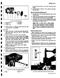
Spring should be compressed to 111 1 g at which Leight it should check 71 to 81 lbs Weak springs affect power and economy and hould be replaced if not within |
|
 |
care not to damage clutch fork 6 3emove clutch shaft DIFFERENTIAL CARRIER A 99Y h 71 6 FC WARD FORK ASSY i i F fAINING SPRING DIFFERENTIAL MAIN SHAFT 1r I I 9 I FORWARD |
|
 |
properly seats the bear I i gs in their races without undesirable looseness or 1 ghtness st 71 ySTEERING GEAR i FITMAN ARM STEERING CONNECTING ROD RELAY ARM ASSY ELAY |
|
 |
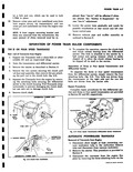
Pull the side cover with the pitman shaft from the housing fig 4 12 J P 71 Fig 4 12 Removing Pitman Shaft NOTE If the sector does not dear the opening in the housing |
|
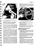 |
71 Fig 4 5 Removing Pitman Arm With Tool J 6627 tion until stopped by gear and then back off one turn of the steering wheel CAUTION Do not turn the wheel hard against |
|
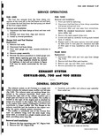 |
shown in Figure 9 44 may be easily constructed for this purpose EXHAUs CORVAIR 500 71 GENERAL The exhaust system on all Corvairs is a single unit which includes the exhaust pipes muffler and tail |
|
 |
Series Cor air 95 and Greenbrier 1200 Series I CORVAIR 500 71 Ir Page Veh de Dimensions 1 1 I Ma l Indentification 11 1 1 Enp ne Data Gea and Control Ratios |
|
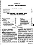 |
Transmission Corvair 95 and Greenbrier 1200 Series Three Speed Transmission Four Speed Transmission CORVA R 500 r 71 THREE SPEED n Page General Description 6D 1 Maintenance and Adjustments 6D 3 Lubrication 6D 3 Shift |