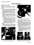
specifications J 88 Fig 70 Installing Spindle Support Outer Bearing IERATIONS J 7817 i i Fig 71 Installing Spindle Support Inner Bearing 2 Install wheel spindle bearing cups in the support using Tool

| Book | Page | Context |
|---|---|---|
|
|
using Tool J 8850 for outer bearing and Tool J 7817 for inner bearing fig 70 and 71 3 Remove spindle outer bearing race and roller assembly using split plates J 8331 as shown ... specifications J 88 Fig 70 Installing Spindle Support Outer Bearing IERATIONS J 7817 i i Fig 71 Installing Spindle Support Inner Bearing 2 Install wheel spindle bearing cups in the support using Tool |
|
|
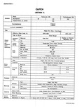
Flat Spring Steel between Rings Woven Asbestos 8 00 9 12 8 00 6 12 49 00 71 8 135 Cast Iron 11 6 Single Row Ball ked with Temperature High Viscosity Grease Sintered Powdered |
|
|
TOWARD i v v v S v 71 VENT HOLE INNER TUBE Fig 66 Filling Tool with Oil 3 Start engine If engine is cold allow to run for 2 to 3 minutes The automatic |
|
|
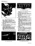
exhaust manifolds exhaust manifold clamp french locks and nuts Using a plastic hammer t p 1 Fig 71 Seating Push Rod Tubes I 1 L Fig 72 Installing push Rod Guides manifold into place while |