| Book |
Page |
Context |
 |
 |
Flywheel Housing 6 51 Cleaning and Inspection 6 51 Seal Replacement 6 51 Crankshaft g 52 Clearting and Inspection 6 52 Disassembly 6 52 Assembly 6 53 Main bearings 6 53 Inspection 6 53 Checking |
|
 |
Axle 3 27 3 55 r Upshifts MPH Minimum Throttle 14 18 12 15 Full Throttle 48 52 42 48 Part Throttle Detent Touch 35 44 33 40 Downshifts Closed Throttle ...
Part Throttle Detent Touch 24 33 22 30 Matrual Low Inhibited 56 81 52 |
|
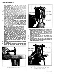 |
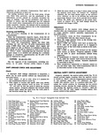
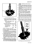
suitable spring scale to check clearance between the REAR ball and the wobble plate fig 52 of the No 1 piston Use aj suitable combination of feeler gauge leafs until ...
between the REAR thrust bearing and the upper outer rear thrust race Use a suitable combination Fig 52 Checking Clearance Between Rear Ball and Wobble Plate of fleler gauge leafs so that |
|
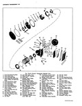 |
01bl 50 48 52 49 46 57 ss 59 rglide Exploded View 30 Transmission Throttle Valve 44 Of I Pan Gasket Leveir and Shaft Assembly 45 Oi I Pan 31 Monlwl Valve Lever ...
Governor Drive Gear 51 Low Servo Piston Cushion 35 Turbine Shaft Front Bushing Spring 36 Turbine Shaft 52 Low Servo Piston Cushion 37 Turbine Shaft Rear Bushing Spring Seat 38 Convherter Assembly 53 Low Servo |
|
 |
52 ...
Used 50 Thrust Washer Detent Gop Gasket 51 Reverse Idler Gear Bearing Race I Detent Cap 52 Reverse Idler Gear Bearing Top Cover Torrington 3 Top Cover Attaching Screws 53 Reverse Idler Gear 8 Used |
|
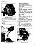 |
over a long and a short stud for each cylinder and retain with cylinder head nuts fig 52 r r i v c I Fig 52 Cylinder Holding Fixture |
|
 |
PUMP PRESSITRS PSn Range Selector Position Condition R N D L At idle 16 Hg 104 122 52 64 52 64 94 105 At idle with vacuum hose disconnected |
|
 |
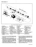
Return Spring 37 Pinion Shaft Rear Oil Seal 51 Clutch Drum Piston 37A Rear Selective Thrust Washer 52 Clutch Drum Hub 38 Pinion Shaft Bushing 53 Clutch Drum Selective Thrust 39 Rear Pump Wear Plate |
|
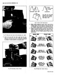 |
analyze the results relative to the following data Figure 51 provides gear tooth nomenclature and Figure 52 illustrates the various contact patterns which mav be experienced DRIVE SIDE COAST SIDE HEEL TOE TOE HEEL EXAMPLE |
|
 |
line is callec the flank The space between the meshed teeth if referred to as backlash Figure 52 shows correct and incorrect contact patterns For illustrative purposes coast side oi gear contact is shown Drive |
|
 |
press so turbine wheel hub rests on press plate 15 Install the shaft sleeve fig 52 impeller shim determined in Step Sf and start the impeller on the turbine shaft 16 Press the impeller onto |
|
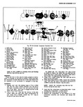 |
Inlet Tube 51 Rear Head to Shell O Ring Retaining Nuts 40 Oil Inlet Tube 52 Compressor to Connector 41 Moinshaft Rear Bearing CY Rings To install the O ring place 1O ring on tool |