| Book |
Page |
Context |
 |
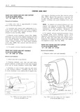 |
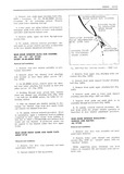
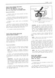
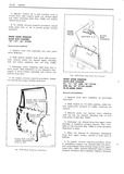
FRONT SEAT CENTER ARM REST AND CURTAIN rest support zittiiching screws then remove screws 35 38 46 48 68000 SERIES 1H50 Repeat this operation on opposite side 37 39 AND 67 STYI ...
lH49 then remove arm rest and cur SGM Fnom SEAT csmzn ARM mast supponr 35 38 46 48 68000 SERIES 4 To insttill reverse removal procedure 37 39 AND 67 STYLES FRONT SEAT CENTER ...
REST ASSEMBLY R I d I 35 38 46 48 68000 SERIES 37 39 AND 67 g Y Eg l Remove center arm rest assembly Rem v I rind Irrs lI i n 1 Place |
|
 |
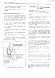
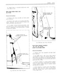
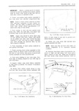
proper alignment AND ALL 69 STYLES EXCEPT with door window raise door window Loosen rear 38 48 68000 SERIES run channel lower adjusting stud nut adjust channel as required and tighten ...
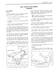
procedure FRONT DOOR WINDOW ADJUSTMENTS ALL lI 35 AND 45 STYLES AND ALL 69 STYLES EXCEPT 38 48 68000 SERIES FRONT DOOR WINDOW REGULATOR Adjustments have been provided to relieve a MANUAL OR ELECTRIC binding ...
door glass due to iiiisalignment of the glass ALL 39 STYLES AND 38 48 run channels The glass can also be adjusted to 68000 SERIES 69 STYLES correct a rotated cocked door window assembly |
|
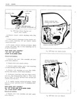 |
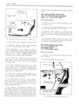
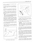
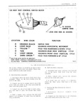
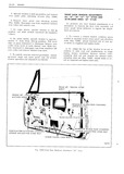
properly positioned REAR DOOR LOCK ASSEMBLY Fig ID78 Door Lock Remote Conrrol EXCEPT 38 48 68000 SERIES Removal ond Instullution l Remove rear door trim assembly and inner INSIDE LOCKING ROD panel water deflector ...
deflector REAR DOOR LOCK ASSEMBLY lakh ALL 39 STYLES AND 38 48 68000 SERIES 69 STYLES EXCEPT 68069 I I4 Removal nd Installation 1 Remove door trim assembly and inner panel water deileotor Fig ID79 |
|
 |
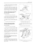
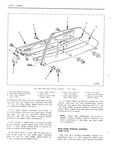
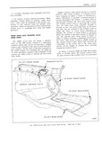
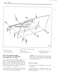
DOORS ID 53 3 Remove rear guide upper attaching bolts Fig 1D7l g Locations A for 38 48 68000 Series ELTL Ag l g5LjO g HANNEL Locations B lor remaining styles Remove rear guide lower ...
GLASS RUN cHANNEL IO lAl ONARY l Au ss 4s 69 srYu2s FRAME SCREWS E EXCEPT 38 48 68000 SERIES Remvqn uma nn u a f Il Remove rear door window assembly |
|
 |
trim B T REAR SEAT BACK CENTER ARM REST AND CURTAIN g I2 x 26 38 46 48 68000 SERIES we JX Rem v I u s nI a A E T CURTAIN l Lower ...
rest Fig lH52 Re I Sem Back Arm Rest d Homes Plate flipper forward 26 38 46 48 68000 Series |
|
 |
rubber ad 1 Spacer Part No 4421823 or equivalent hesive caulking compound that adheres to both the 48 X g X 1 0 flat glass and back window opening pinchweld flange Applied to the glass ...
gpgtpgy part No 4410043 or equivalent terial begins to cure soon after exposure to air 48 X 24 X 74 insert Due to this fast curing characteristic installation ot the glass into the body opening |
|
 |
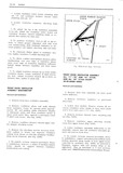
CPIAPIcP iLw CAPIAJ Q REAR DOOR WINDOW FRONT GUIDE FRONT GLHDE ALL 39 STYLES AND ALL 38 48 68000 UPPER BON SERIES 69 STYLES EXCEPT 68069 Id V M U 4 I Removal and InsI ...
WINDOW REAR GUIDE frame lower adjustin studs Fi lD68 AI I 39 STYLES AND AI I 38 48 68000 SERIES These attaehments can be adjusted in eonibina 69 I STYLES EXCEPT 68069 tion or individually |
|
 |
ELECTRIC ALL 37 39 57 67 STYLES AND 2 Remove bolts securing door inner panel cam 38 48 68000 SERIES 69 STYLES UA Fig lD35 Disengage cam from reuulator balance arms and remove ram from ...
ADJUSTMENTS ALL 37 39 57 67 STYLES AND l Raise door window Rcinovc door trim as 33 48 68000 SERIES 69 STYLES sembly and detach inner panel water deflectot suf ficiently to gain access |
|
 |
STYLES AND BALANCE ARM H MOTOR ALL 69 STYLES EXCEPT 38 48 68000 SERIES nemowi and In II ea l Remove front door trim assembly and inner A r 1 Ifl panel water deflector ...
position of the regulator lift FRONT DOOR WINDOW arm GLASS RUN CHANNEL ALL 39 STYLES AND 38 48 68000 IMPORTANT DO NOT drill into the motor SIERIES 69 STYLES housing part of which is indicated |
|
 |
rnLM stick sous 48 Fig 5 I 39 Top Compartment Bog Tied to Center Bow Fig 5 I 40 Reur Quarter Trim Stick |
|
 |
TACKS trim material along forward edge of front roof rail A rig 5123 7 7 rr 48 Unlock top from windshield header and apply W rrr nitrile cement or neoprene type weatherstrip ad ii hesive |
|
 |
port on opposite side of body K 30 5 32 Forward gage hole in dash jylmt S 48 Gage hole in lower ilange of rear brBc spring front support |
|
 |
back curtain and compartment bag material from body and place on a clean protected Fig 2 I 48 L IIng Edge of Top Material surface |
|
 |
REST DARK GREEN CONTROLS FORWARD8 UP CYCLE YELLOW FIELD CONTROLS REARWARD8 DOWN CYCLE I825 Hg I1 48 L5 I6 25 26 45 4 2 480L O Serie end uf wire Failure is caused |
|
 |
ELECTRICAL ll 33 SIX WAY SEATS All SERIES DESCRIPTION Fuse Bleek 45 46 48 68000 Series The sent adjusters are actuated by a 12 vfilt 35 36 38000 Series Only In addition |
|
 |
LIGHT GREEN SOLENOID VERTICAL MOVEMENT IBA Fig IL4I F0ur Way Sem Switch Block 25 26 45 46 48 68000 Series I2 GAUGE JUMPER WIRE Q JOIN ONE END J QQ A5 SHOWN |
|
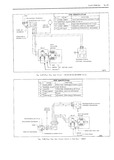 |
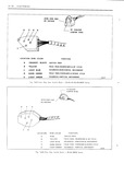
smmonus RED GREEN MOTOR LEADS YELLOW 1673 Fig IL37 Few Way Sear Circuif 25 26 45 46 48 68000 SerIes WIRE IDENTIFICATION m c0L0 ruwcncn 7 DARK GREEN FIELD FEEDVFORWARDBIDOWN CYCLE IA ORANGE BLACK FEED |
|
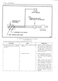 |
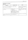
YELLOW FEED ORANGE BLACK STRIPE 1818 Fig lL34 E ee ie Hmizomul Sear Cimnir Diagram 45 46 48 68000 Series IJ Typical Failures and Corrections of Horizontal Seat Circuit CONDITION CAUSE CORRECTION The seat motor |
|
 |
IttIi iu friuue and are energized by u control switch 36 38000 series and Figure 1L34 mr 48 68000 installed in the seat side panel or in the door arm series |
|
 |
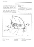
operation GLASS RUN CHANNEL ALL II 35 AND 45 STYLES oAND ALL 69 STYLES EXCEPT F 38 48 68000 sER E5 V l Removal und InsI I Ii n I I L l Remove front |
|
 |
back remove four HANGERPLATE AND LINKAGE screws securing arm rest hanger plate to seat 26 38 46 48 68O0 SERIES back supports then carefully remove arm rest and hanger plate assembly from seat back |
|
 |
48 DOORS |
|
 |
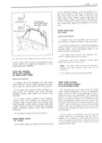
Anqeiimem F I g y REAR DOOR WINDOW ASSEMBLY A 3I5 45 69 STYLES i EXCEPT 38 48 68000 SERIES AL I v Removal mid Inslulluticn il 3 NGE TO Remove door trim assembly |
|
 |
1D54 t e 1 0001 1 1 1 1W 1e ewes Except 38 48 68000 series 1 wz11 1 1 A5 cm1 1 1 5 Remote O 1 1 8 Gloss Run c11 e1 Emends |
|
 |
System will not hold vacuum Excessive leakage in any one of Isolate leaking wnipunent with fer 48 hours the following leak down testing device as de 1 Remote valve scribed previously in this 2 Door |
|
 |
System will not hold vacuum 1 Excessive leakage in any one 1 Actuate system through sev for 48 hours of the following units can be the eral lock and unlock cycles and cause recheck leakage |
|
 |
connects the vacuum storage VALVE ASSEMBLY tank with the remote control valve assembly 35 36 38 48 68000 SERIES The remote control valve is attached below the Removul und lnst lI ion right hand defroster |
|
 |
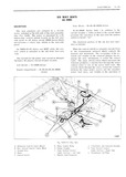
LEFT REAR DOOR 1688 Fig IC 48 Vacuum Door Lock Vacuum Hose Routing Right Side of Body |
|
 |
from down LOCK ACTUATOR ASSEMBLY travel stop and operate glass to full down position 35 36 38 48 63 0 5ER E 2 On styles with ventilator lower moldings re The actuators that operate |
|
 |
IQQ6 Fig I I 46 Sp er Stick Insmllqrion Fig I I 48 Che king Trim Stick Fillers |
|
 |
WINDOW ADJUSTMENTS rear guide plate attaching screws Fig 1D4 ALL 37 39 57 67 STYLES AND 38 48 68000 SERIES 69 STYLES 4 Remove inner panel cam attaclung screws Fig lD40 Disengage cam from regulator |
|
 |
STYLES AND bolts do not exceed torque of 50 inch pounds 4 38 48 68000 SERIES 69 STYLES foot pounds Also when replacing door glass replace glass spacers The front door window assembly consists |
|
 |
STYLES desired then tighten T shaft bolt AND ALL 69 STYLES EXCEPT 38 48 68000 SERIES Removal und lnst ll i n FRONT DOOR VENTILATOR ASSEMBLY WEATHERSTRIP 1 Remove door trim assembly and inner panel |
|
 |
been torn cut or damaged 38000 SERIES wcwm apply waterproof body tape to both sides of deflee 48 458000 SERIES SIMIVLAI tor over damaged area to prevent water from wicking on uneoated side of defleutor |
|
 |
Styles in m m E Ir m N the 15 16 26 35 36 38 45 46 48 and 68000 M E m I U NUM E Series This information is current as of time |
|
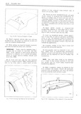 |
binding extends past Psleutl li iS scam 1 1 2122 i v rt ra t l 48 At tront roof rail pull top trim material NOTE Any tid Ilnki mule |
|
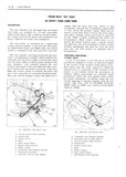 |
familiar with the seat lit t ircu it See Figs 1L3 7 for 25 28000 45 46 48 l Yl rtl B 68000 lL38 for 48467 only lL39 |
|
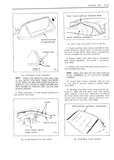 |
PANEL l53O k 77 930 Fig 5 l 46 Che kirig Trim Srick Fillers Fig 5 l 48 Buck Curtuln Insmlled |