| Book |
Page |
Context |
 |
 |
Assembly 6 46 Piston and Connecting Rods 6 46 Piston Rings 6 47 Cylinder 6 48 Crankcase 6 48 Cleaning and Inspection 6 48 Repairs 6 49 Oil iPick Up Screen and Tube Replacement |
|
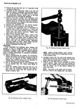 |
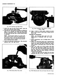
casting webs 5 Examine the mechanism for any obvious damage 6 Remove the suction crossover cover fig 48 7 If desired the mechanism may be assembled checking Cage J 9397 and operated on a motor ...
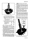
free from the dowel pins and discharge crossover tube using a fiber block and mallet fig 48 Discard the discharge crossover tube Fig 46 Removing Suction Crossover Cover Fig 47 Unseating Diachorge Crossover Tube NOTE ...
front of the piston may be identified by a notch in the casting web See Figure Fig 48 Separating Cylinder Halves |
|
 |
CHART Axle 3 27 3 55 r Upshifts MPH Minimum Throttle 14 18 12 15 Full Throttle 48 52 42 48 Part Throttle Detent Touch 35 44 33 40 Downshifts Closed Throttle ...
Full Throttle 42 48 38 44 Part Throttle Detent Touch 24 33 22 30 Matrual Low Inhibited |
|
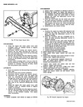 |
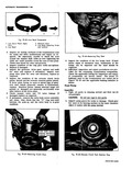
attaching bolts through the access hole at the 12 o clock position in the converter housing fig 48 The converter may be rotated by prying against the starter gear teeth on the converter housing with ...
synchromesh transmission equipped vehicles Adjust and connect clutch rod and connect clutch return spring Fig 48 Transaxle Separated from Engine |
|
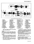 |
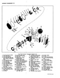
48 47 46 45 44 43 42 38 37 Fig 39 Six Cylinder C 1 Shaft Nut 14 Shaft Seal Seat 2 Clutch Hub Retainer Ring Retainer Ring 15 Shaft Seal Seat 3 Spacer ...
Piston Ring 47 Rear Head to Shell 36 Drive Shaft and Wobble O Ring Plate Assembly 48 Strainer Screen 37 Rear Thrust Race and 49 Compressor Rear Head Bearing Pack 50 High Pressure Relief |
|
 |
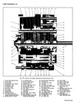
01bl 50 48 52 49 46 57 ss 59 rglide Exploded View 30 Transmission Throttle Valve 44 Of I Pan Gasket Leveir and Shaft Assembly 45 Oi I Pan 31 Monlwl Valve Lever ...
Attaching Screws 32 Trarqmission Throttle Valve 48 Low Servo Piston Retaining Inner Lever Clip 33 Govlmor Gear Thrust 49 Low Servo Piston Spacer 50 Low Servo Piston Ring 34 Governor Drive Gear 51 Low Servo |
|
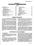 |
Turbine Shaft 7 46 Pump Shaft 46 Rear Pump and Reverse Piston Assembly 7 46 Converter 7 48 Planet Carrier Assembly 7 48 Assembly of Transmission 7 50 Front Pump Thrust Washer Determination |
|
 |
48 47 f 46 45 44 43 42 41 40 Fig 7B 1 Corvpir Four Speed T nsm l Clutch Gear Bearing Cover 15 lst Blacker Ring 2 Clutch Gear 16 Reverse Shifter Lever ...
Detent and Interlock 47 Mainshaft Roller Bearings Channel Cap 34 Front 38 Rear 36 First Gear Sleeve 48 Clutch Gear Bearing 37 1 2 Sy chronizer Hub 49 Clutch Gear Bearing 38 ynchrdnizer Key Snap |
|
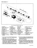 |
48 xo 47 46 50 45 44 3 3w 38 34 I 3 Fig 7A 13 Manual rarun 1 Input Shaft 16 Clutch Gear 2 2 Mairlshaft Bearing 17 Snap Ring 31 3 Moinshaft Bearing ...
Bearing Washer L First and Reverse Shift Fork 47 Countergear Front Needle Shaft Bearings i Detent Spring 48 Countergear i Detent Ball 49 Countergear Rear Needle F First and Reverse Fork Bearings and Thrust |
|
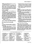 |
Plate 31 Stator 46 Valve Body 32 Turbine 47 Oil Pick up Pipe 33 Engine Flex Plate 48 Low Servo Piston 34 Stator Cam Race 49 Low Servo Piston Cushion 35 Converter Hub Seal Spring |
|
 |
turbine shield to install with three projections spaced over flat areas of the spring ring fig 48 then install C clamps to hold spring ring compressed 12 Lubricate the turbine shaft seal ring groove with |
|
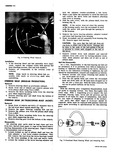 |
Turn the nut upside down and rotate the wormshaft back and forth until all 48 balls have dropped out of the nut into a clean pan With the balls removed the nut can be pulled |
|
 |
48 2 3 4 Fig 7E 22 Low Band Components 1 Low Servo Piston Apply 3 Reaction Strut Strut 4 Low Band Adjusting Scre 2 Low Band and Locknut 1 2 Inspect all mating surfaces |
|
 |
center punch restake the pinion s at four places on both ends of planet carrier fig 7E 48 Assembly of Transmission NOTE The following steps apply only if the transmission is separated from the Power |