| Book |
Page |
Context |
 |
 |
Hinge 10 46 Lid Support 10 46 Lid Latch 10 46 Lower Gutter Sealing Strip 10 47 Exterior Mouldings 700 Models 10 47 Removal and Installation 10 47 Windshield Pillar Drip Moulding 10 47 Engine ...
Compartment Lid Outer Panel Moulding 10 47 Front Compartment Lid Outer Panel Moulding 10 47 Front Fender Lower Moulding 10 47 Roof Drip Moulding Front Scalp 10 47 Roof Drip Moulding Rear Scalp 10 47 |
 |
 |
Bearings 6A 45 Valve Lifters 6A 46 Flywheel Housing Seal 6A 46 Engine Assembly Engine Removed 6A 47 Crankshaft 6A 47 Camshaft 6A 47 Timing Gear Marks 6A 48 Camshaft End Play 6A 49 Timing |
 |
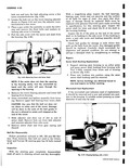 |
bushing from housing with Tool J 1614 inserted from lower end of housing as shown fig 4 47 2 Press new bushing into position using the same sector shaft bushing used for removal NOTE Service ...
housing A suitable socket pressing on outer diameter of seal may be used i r Fig 4 47 Pressing Bushing with J 1b14 |
 |
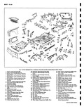 |
Seat Pan Duct 37 Plate Engine C 22 23 21 1 24 41 21 1A 13 p 47 45 NY 70 117 4 O OF43 CIL 1 0 MMM11fa ...
Support Engine Mount Lower 45 Plate Engine Mount Tapped i Panel Reinforcement 46 Panel Rear End Inner 47 Support Engine Mount Upper ngine Compartment 48 Panel Rear End Outer tinge lower 49 Brace Rear Cross |
 |
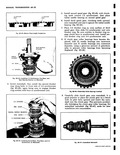 |
clutch gear This prevents accidentally dislodging the clutch gear roller bearings Set assembled mainshaft fig 6D 47 aside for later installation into transmission n Fig 6D 47 Assembled Malnshaft |
 |
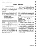 |
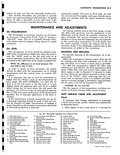
PUMP PRESSURES PSII Condition Range Selector Position R N D L At idle 16 Hg 81 98 47 57 47 57 71 82 At idle with vacuum hose disconnected |
 |
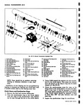 |
47 7 4 6 4 S 44 33 38 34 Fig 6D 13 Manual Ti 1 Clutch Shaft 16 Clutch Gear 2 Main Shaft Bearing 17 Snap Ring 3 Main Shaft Booting Retainer 1B Clutch ...
Interlock 46 Counter Gear Front Bearings 33 Roll Pin spacer 34 first end Reverse Shift Fork 47 Counter Gear Front Needle Shaft Bearings 35 Defeat Spring 4 Counter Gear 36 DeNnl Bell 49 Counter Gear |
 |
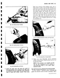 |
press red spring stopper and squeeze the balance of cement into the tire fig 3 47 Retract metal tube with continuous clockwise turning and pulling action fig 3 48 Do not pull but trim ...
repair is now complete and the tire is ready for immediate use 1 wppr 0 Fig 3 47 Applying Remainder of Cement with Plug Inserted Fig 3 48 seating Plug to Complete Repair 9 Clean |
 |
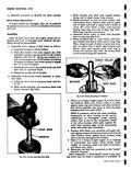 |
Slide clutch assembly onto armature shaft with pinion outward fig 8 41 SNAP RING GROOVE Fig 8 47 Forcing snap Ring Over ShM c Slide retainer onto shaft with cupped surface facing end of shaft ...
wood Hit wood block a blow with hammer forcing snap ririg over end of shaft fig 8 47 Slide snap ring down into groove e Assemble thrust collar on shaft with shoulder next to snap |
 |
 |
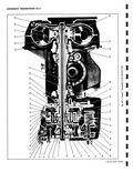
Pump 44 Ring Gear 30 Starter Gear 45 Valve Body Ditch Plate 31 Stator 46 Valve Body 47 Oil Pick up Pipe 32 Turbine 48 Low Servo Piston 33 Engine flex Plate 49 Low Servo |
 |
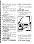 |
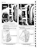
location of hinges on front body hinge pillar 3 Loosen hinge attaching bolts shown in Figure 10 47 Shift door to desired position then tighten hinge attaching bolts 4 Check door for proper alignment |
 |
 |
UPPER HINGE ATTACHING BOLTS r Sx i l x LOWER HINGE ATTACHING BOLTS w Fig 10 47 Front Door Hinge Attachment at Cowl required adjust door as described under Front Door Adjustments 3 Install cowl |
 |
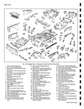 |
Panel Left anger Opening 46 Filler Rear End Inner Panel At Bumper Depression Left i Panel Reinforcement 47 Panel Rear End Inner ngine Compartment 48 Housing Rear End Panel License Plate linge Lower 49 Filler |
 |
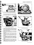 |
ring are a the 12 o clock position then install the retaine ring clip inset fig 6E 47 on thick reaction plato between ends of snap ring 6 With the rear of the transmission case |
 |
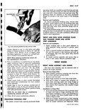 |
remove bolts securing upper and lower hinges to front body hinge pillar as shown in Figure 10 47 then remove door assembly with attached hinges from body Installation to Hinge Pillar 1 As an anti |
 |
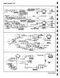 |
SPLICE 8A1 11 GA DK GREEN 47 W OIA L12 GA RED BACKING LAMP SWITCH ITCN IN 11 W BROWN SPLICE IGNITION SWITCH STANDARD TRANSMISSION CIRCUIT SHOWN IN 1VHEN A F O A INSTRUMENT PANEL |
 |
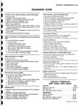 |
seating CORVAI R POWERGLIDE SHIFT POINT MPH CHART UPSHIFTS MPH Minimum Throttle 10 12Y2 Full Throttle 41 47 Part Throttle Detent Touch 34 41 DOWNSHIFTS Closed Throttle 8 12 Full Throttle 38 44 Part Throttle |
 |
 |
Corvair 500 700 an SPECIFI See SecTion 16 for Fuel fications SPECIAI n I i Fig 9 47 1 J 8370 Rochester Model H Ch a Float Level and Dra b Choke Unlooder |
 |
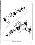 |
47 58 o o P 59 Pow rglide Exploded View CORVAIR SHOP MANUAL |
 |
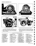 |
Shaft Seal 45 Oil Pon 30 Transmission Throttle Valve 46 Oil Pan Attaching Screws Lever and Shaft 47 Oil Pick up Pipe Attaching 31 Manual Valve Lever Screw 32 Transmission Throttle Valve 48 Low Servo |
 |
 |
47 |
 |
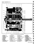 |
Shift Fork Shaft Detent 34 Drain Plug Roll and Spring 35 3 4 Detenf and Interlock 47 Clutch Clear Roller Bearings 133 Channel Cap Front 37 Near 36 First Gear Sleeve 48 Clutch Oear Rearing |
 |
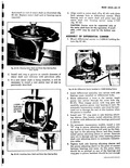 |
While differential is loose in the carrier insert pinion into carrier through the cover hole fig 6C 47 Then engage pinion with ring gear and carefully position pinion rear bearing in race On automatic transmission |
 |
 |
Lock Tab 45 Pinion Adjusting Sleeve Seal Ring embly 46 Pinion Shaft Bushing Auto Trans only 47 Differential Components Ice A Ring Gear Bolts and Lock Washers diusfing Sleeve 8 Differential Cover Aiusting Sleeve Seal |
 |
 |
Install front shrouds figures 6A 15 and 16 Install left and right side shields fig 6A 11 47 Install upper shroud assembly fig 6A 12 Turn blower and check clearance while tightening upper shroud retaining |
 |
 |
47 |


