| Book |
Page |
Context |
 |
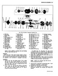 |
47 46 45 44 43 42 38 37 Fig 39 Six Cylinder C 1 Shaft Nut 14 Shaft Seal Seat 2 Clutch Hub Retainer Ring Retainer Ring 15 Shaft Seal Seat 3 Spacer 16 Shaft ...
Pump Drive Gear 34 Piston Rear Drive Boll 46 Oil Pump Driven Gear 35 Piston Ring 47 Rear Head to Shell 36 Drive Shaft and Wobble O Ring Plate Assembly 48 Strainer Screen 37 Rear |
 |
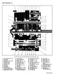 |
47 f 46 45 44 43 42 41 40 Fig 7B 1 Corvpir Four Speed T nsm l Clutch Gear Bearing Cover 15 lst Blacker Ring 2 Clutch Gear 16 Reverse Shifter Lever 3 Countershaft ...
Shift Fork Shaft Detent Detent Ball and Ball ankl Spring Spring 35 3 4 Detent and Interlock 47 Mainshaft Roller Bearings Channel Cap 34 Front 38 Rear 36 First Gear Sleeve 48 Clutch Gear Bearing |
 |
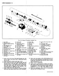 |
47 46 50 45 44 3 3w 38 34 I 3 Fig 7A 13 Manual rarun 1 Input Shaft 16 Clutch Gear 2 2 Mairlshaft Bearing 17 Snap Ring 31 3 Moinshaft Bearing Retaining ...
Interlock 46 Countergear Front Needle t Roll Pin Thrust Bearing Washer L First and Reverse Shift Fork 47 Countergear Front Needle Shaft Bearings i Detent Spring 48 Countergear i Detent Ball 49 Countergear Rear Needle |
 |
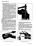 |
with a pencil 2 Use an old discharge tube to drive discharge tube out of cylinder fig 47 Drive from REAR of cylinder 3 Drive the cylinder halves apart and free from the dowel pins ...
block and mallet fig 48 Discard the discharge crossover tube Fig 46 Removing Suction Crossover Cover Fig 47 Unseating Diachorge Crossover Tube NOTE Before driving cylinder apart position wobble plate toward front of compressor |
 |
 |
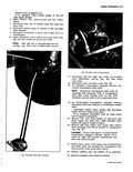
Disconnect TV rod at carburetor and vacuum hose at balance tube Depress 0 0 45 47 84 105 accelerator to W O T By disconnecting TV rod at carburetor engine remair at idle speed throughout |
 |
 |
Remove nuts from engine rear mount then remove bolts attaching front mount bracket to transmission case fig 47 CAUTION Do not loose spacer on synchromesh transmission equipped vehicles Spacer is located on right bolt between |
 |
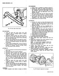 |
47 Front Mount Bracket Bolts SYNCHROMESH a Using the engine lift lower power train until transaxle rests on suitable blocks to supp o weight of transaxle b Disconnect starter wiring and remove starter c Remove |
 |
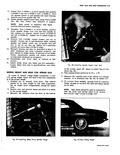 |
settle to its normal height 3 Measure the distance from the floor to the bottom 47 1 aiq J 21843 Y Fig 67 Installing Wheel Drive Spindle Flange |
 |
 |
Connecting Rod 6 46 Assembly 6 46 Piston and Connecting Rods 6 46 Piston Rings 6 47 Cylinder 6 48 Crankcase 6 48 Cleaning and Inspection 6 48 Repairs 6 49 Oil iPick Up Screen |
 |
 |
Ring Gear 30 Starter Gear 45 Valve Body Transfer Plate 31 Stator 46 Valve Body 32 Turbine 47 Oil Pick up Pipe 33 Engine Flex Plate 48 Low Servo Piston 34 Stator Cam Race |


