| Book |
Page |
Context |
 |
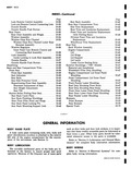 |
Rear Seat Compartment Trim 10 42 Side Trim Replacement 10 42 Rear Trim and Insulation Replacement 10 43 Front Trim and Insulation Replacement with Folding Seats i0 43 Division Panel Trim and Insulation Replacement ...
43 Wheelhouse Trim Replacement 10 43 Rear End 10 43 Back Window Assembly 10 43 Engine Compartment 10 45 Lid 10 45 Lid Hinge 10 46 Lid Support 10 46 Lid Latch 10 46 Lower |
 |
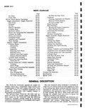 |
Cleaning Inspection and Repairs 6A 42 Stud and Thread Repairs 6A 42 Oil Level Gauge Tube 6A 43 Blower Bearing 6A 43 Main Bearings 6A 43 Bearing and Journal Inspection 6A 43 Main Bearing Clearance ...
43 Connecting Rod Bearings 6A 45 Valve Lifters 6A 46 Flywheel Housing Seal 6A 46 Engine Assembly Engine Removed 6A 47 Crankshaft 6A 47 Camshaft 6A 47 Timing Gear Marks 6A 48 Camshaft End Play |
 |
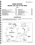 |
MAIN WIRI DIAGRAMS 00 and 900 SERIES JDEX Page Headlamp Circuit 8 42 Tail Lamp Circuit 8 43 Horn Circuit 8 43 Windshield Wiper Circuit 8 43 Cigarette Lighter Circuit 8 43 Glove Compartment Lamp |
 |
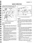 |
separate the inlet assembly from the filler pane by removing nuts C Figures 11 42 and 11 43 fron the filler panel studs 3PERATIONS 6 00 1a FILLER PANEL SLEEVE LH ONLY ASSEMBLY AS SHOWN ...
INLET DUCT ASSEMBLY PLAIN WASHER CLAMP HOSE BOOT NUT L W CLAMP ASSEMBLY Fig 11 43 Heater Housing Filler Panel AHachmenf Inspection The air inlet assembly may be inspected for damage The condition ...
upper duct attaching screw B Figure 11 42 5 Tighten nuts C Figures 11 42 and 11 43 6 Replace the hot air hoses and tighten the attaching clamps 7 Replace the control cables |
 |
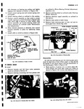 |
Section 10 2 Remove steering connecting rod from pitman arm r I i j Fig 4 43 Romoval of Steering War from Vehicle as outlined in Worm Bearing Preload Adjustment operation two 3 Remove steering ...
dash clamp 6 Remove bolts retaining gear to body rail and remove gear from vehicle fig 4 43 WORM BEARING ADJUSTER WORMSHAFT LOCK NUT BALLS AND GUIDES r WORM BEARING WORM BEARING BALL ...
using tool J 6632 as shown in Figure 4 45 Loosen lash adjusting screw T Fig 4 43 Pulling Pitman Arm with J 663Z CORVAIR SHOP MANUAL |
 |
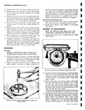 |
either replace converter or repair welds as re kv IV 4 p q A Fig 6E 43 Installing Converter Hub Bushing with J 8360 1 and Handle J 7079 2 quired If welds are repaireu ...
damage converter bore 2 Install new bushing using J 8360 1 as illustrated fig 6E 43 ASSEMBLY OF TRANSMISSION NOTE The following steps apply only if the transmission is separated from the Power Train |
 |
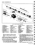 |
onsmission supleded View 28 Second and Third Speed Shift 43 Top Cover Attaching Screws Fork Shaft t Used 49 Delenl 8011 44 Reverse Idler Gear Shaft lock 30 Detent Spring Fin 31 Roll Pin 43 |
 |
 |
SERVICE C FUEL LINES The fuel line fig 9 43 extends from a hose clamp connection at the tank gauge sending unit through the covered tunnel to a point just ahead of the rear cross ...
disassembly the lines should be disconnected and blown out i t T r v Fig 9 43 1 Gas Tank 2 Filler Pipe iPERATIONS Removal 1 Remove the tunnel cover 2 Disconnect the hose clamp |
 |
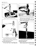 |
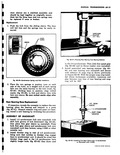
surface in pinion shaft during removal 2 Install new bushing with J 8333 as shown fig 6C 43 A stop is provided on the tool to press the bushing to the prescribed depth ...
43 Installing Pinion Shaft Bushing with J 8333 Stator Shaft and or Pinion Rear Bearing Race Replacement 1 Remove stator shaft and pinion bearing cup from carrier by placing carrier in a press and pressing |
 |
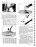 |
Cleaning Puncture with Cleaning Needle Fig 3 43 Preparing Plug for Use each retraction Make sure the small circular cutout resulting from operation shown in Figure 3 41 has been removed Lever the needle ...
until the head of the plug is seated tightly against the end of the tube fig 3 43 Cut off protruding end of plug stem 6 Prepare the plug insertion tool for insertion of plug |
 |
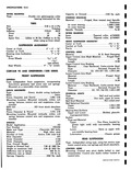 |
Wire Diameter 677 Outer Dimneter 5 154 Pitch Diameter 4 477 Free Overall Height 12 43 Height at Normal load 7 86 1860 lbs Height at maximum load 5 94 3022 lbs Deflection rate |
 |
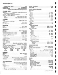 |
Seat Steel Rocker Arm Ratio 1 50 Valve Lash Zero VALVE TIMING Theoretical Turbo Air Inlet Opens 43 BTC Closes 93 ABC Exhaust Opens 87 BBC Closes 69 ATC Tappet Lift Inlet 20926 Exhaust |
 |
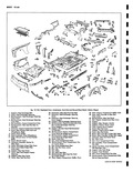 |
Rear End Panel 41 Rail Engine Comportment Rear Cross cehonger Opening Cover 42 Support nine Compartment Side 43 Support Rear Bumper Center Zianger Opening 44 Support Engine Mount Lower 45 Plate Engine Mount Tapped |
 |
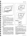 |
BODY CAULKING COMPOUND I t SEALING TAPE Fig 10 43 Wafer Deflector Sealing Along Retaining Slot Area Removal Complete 1 Remove door trim assembly 2 Remove strips of waterproof body tape securing lower corners |
 |
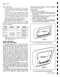 |
deflector from retaining slot then roll deflector back to gain access to door inner panel fig 10 43 I BODY CAULKING I COMPOUND I v I I I SEALING TAPE Fig 10 41 Partial Removal |
 |
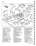 |
Front End and Shroud Sheet Metal Exchanger Opening 42 Reinforcement Rear End Panel Right 43 Reinforcemenf Engine Mount Rear Support changer Opening Cover 44 Plate Engine Mount Tapped ngine Compartment Side 45 Reinforcement Rear |
 |
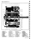 |
Shift Fork 30 1 2 Shift Fork Shaft 42 Shift Finger 31 Interlock 43 Special Snap Ring 32 3 4 Shift Fork Shaft 44 Shifter Shaft Seal 33 3 4 Shift Fork Shaft Defenf Ball |
 |
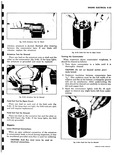 |
warc s Fig B 43 Armature Test for Shorts vibrates armature is shorted Recheck after cleaning between the commutator bars If saw blade still vibrates replace the armature Armature Test for Ground Place one lead |
 |
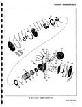 |
43 45 42 50 48 54 52 56 49 46 57 47 58 o o P 59 Pow rglide Exploded View CORVAIR SHOP MANUAL |
 |
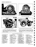 |
Assembly 57 Vacuum Modulator Valve 42 Oil Pick up Pipe O Ring Seal 58 Vacuum Modulator Gasket 43 Oil Pick up Pipe Assembly 59 Vacuum Modulator |
 |
 |
43 |
 |
 |
noted that blocker rings used in the 1 2 synchronizer have slightly longer hubs fig 6D 43 than those used i r IMPROVISED REMOVER wy n 11 fll III11W I ST GEAR SLEEVE SHIFT FORK |
 |
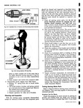 |
placing on growler and holding hack saw blade over armature core while armature is rotated fig 8 43 If saw blade |
 |
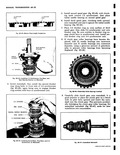 |
BLOCKER 1 2 BLOCKER RING RING Fig 6D 43 81ocker Ring Length Comparison 1h REAR BEARING RETAINER THRUST WASHER 1 ST GEAR 1 2 SYNCRO Fig 6D 44 Installing 1 2 Synchronizer First Gear |
 |
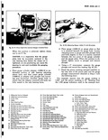 |
only and Speedometer iring Race Drive Gear iring 41 Pinion Front Bearing 42 Pinion Front Bearing Race 43 Pinion Adjusting Sleeve a Auto Trans Type b Manual Trans Type 44 Pinion Front Seal Auto Trans |
 |
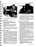 |
cylinder heads torque valve cover screws 30 50 in lbs Oil Filter and Generator Adapter 43 Install a new oil filter and generator adapter gasket on the engine rear housing Install oil filter and generator |
 |
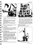 |
43 Tuming Crankshaft using Crankshaft Pulley ecting rod so connecting rod cap and bearing can e removed r I CITE Mark cylinder numbers on each connect i Ig rod and piston to identify for reassembly |
 |
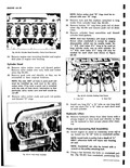 |
pulley attaching bolt 34 Using a bar between the bolts on crankshaft pulley fig 6A 43 turn crankshaft positioning |
 |
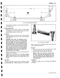 |
Install idler arm and pitman arm to relay rod In stall and tighten nuts to 29 to 43 ft lbs and instal cotter pins CAUTION After relay rod bushings are replaced care must be taken |
 |
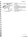 |
l111 SECTION B B Fig 2 43 Door window RoyulaMr r Door Lock Parts Lubricate moving parts of door lock with Lubriplate or equivalent Door Locking Mechanism Apply Lubriplate or equivalent to pivot points |
 |
 |
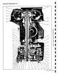
minutes for nsaxle Cross Sectional View 26 Turbine Shaft 42 Long Pinion Gear 27 Front Pump Shaft 43 Reverse Clutch Plate Retaining 28 Converter Hub Bushing Ring 29 Converter Pump 44 Ring Gear 30 Starter |
 |
 |
43 |


