| Book |
Page |
Context |
 |
 |
Exhaust Manifold Sleeves 6 4 Valve Guides 6 4 Stud Replacement 6 Thread Repair 6 43 GENERAL DE The six cylinder over head valve engines covered this section are the 164 cu in engines used ...
crankcase halves has four I CHAN11CAL x Page Vacuum Balance Tube and Plug Replacement 6 43 Choke Coil and Control Rod Replacement 6 43 Assembly 6 43 Valve Lifters Hydraulic 6 44 Disassembly |
|
 |
Install idler arm and pitman arm to relay rod Inst ll and tighten nuts to 29 to 43 ft lbs and install cotter pins CAUTION After relay rod bushing is replaced care must be taken ...
attaching bolts Installation Reverse above removal procedures and torque idler arm nut at relay rod from 29 43 ft lbs The idler bracket should be torqued from 14 20 collision ft lbs Steering Arms becomes |
|
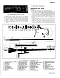 |
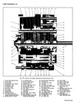
43 1 f Telescoping Mast Jacket 23 Directional Lever 34 Directional Wiring Cover 24 Directional Wiring Connectors 35 Directional Wiring Clamp 25 Upper Snap Ring 36 Screw 26 Steering Shaft Assembly 37 Lower Snap Ring ...
Inner Mast Jacket 41 Felt Sea 31 Stop Bolt 42 Lower Spring and Retainer 32 Lock washer 43 Lower Spring Snap Ring 33 Outer Mast Jacket CCIRVAR SHOP MANUAL |
|
 |
43 I 45 53 51 42 t f 01bl 50 48 52 49 46 57 ss 59 rglide Exploded View 30 Transmission Throttle Valve 44 Of I Pan Gasket Leveir and Shaft Assembly ...
Vacuum Modulator 42 Valve Body Screen O 60 Front Pump Shaft Ringi Seal 61 Downshift Timing Valve 43 Valve Body Screen Assembly |
|
 |
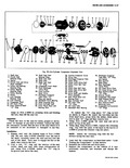
43 42 41 40 Fig 7B 1 Corvpir Four Speed T nsm l Clutch Gear Bearing Cover 15 lst Blacker Ring 2 Clutch Gear 16 Reverse Shifter Lever 3 Countershaft 17 Reverse Shift Fork ...
ission Croso Sectional View 28 Reversel Shifter Head Shaft 42 Shift Finger 29 Interlock Pin 43 Special Snap Ring 30 1 2 Shift Fork Shaft 44 Shifter Shaft Seal 31 Interlock 45 Shifter Shaft |
|
 |
Steering Wheel Nut 25 35 ft lbs Tie Rod End Nut 29 43 ft lbs Tie Rod Clamp Bolts 12 16 ft lbs Idler Arm Mounting Bolts 14 20 ft lbs CTRICAL 12 Candif Number ...
Speed Type Electric Crank Arm Rotation looking at the crank arm CCW Crank Arm Speed No Load 43 rpm Operat lng Voltage 12 VDC Current Draw Free Speed 3 0 amp Max Dry Windshield |
|
 |
Discharge Air Temp at 34 36 38 38 39 40 R H Outlet 40 41 43 43 44 45 When compressor clutch disengages kND ADJUSTMENTS suction pressure shown in the Performance Test chart The adjustment |
|
 |
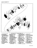
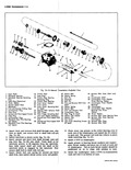
43 42 38 37 Fig 39 Six Cylinder C 1 Shaft Nut 14 Shaft Seal Seat 2 Clutch Hub Retainer Ring Retainer Ring 15 Shaft Seal Seat 3 Spacer 16 Shaft Seal 4 Clutch ...
Crossover 27 Drive Key Tube Rear 0 Ring 28 Discharge Crossover Tube and Spacer 29 Piston Ring 43 Rear Suction 30 Piston Front Drive Boll Reed Plate 31 Piston Front Boll Seat 44 Rear Discharge |
|
 |
43 I f 411111 42 1 10 4 so 49 48 xo 47 46 50 45 44 3 3w 38 34 I 3 Fig 7A 13 Manual rarun 1 Input Shaft 16 Clutch Gear |
|
 |
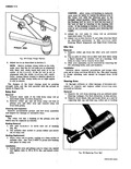
insert b For damage to O ring seal groove o t f V i l q Fig 43 Removing Bearing Retainer Ring |
|
 |
items Battery positive cable terminal and 10 gauge red wire at terminal on body side rail fig 43 Battery negative cable at Delcotron bracket Stkrter wiring at quick disconnect Cylinder head temperature and oil pressure |
|
 |
that position glide Cross Sectional View 26 Turbine Shaft 42 Long Pinion Gear 27 Front Pump Shaft 43 Reverse Clutch Plate 28 Converter Hub Bushing Retaining Ring 29 Converter Pump 44 Ring Gear 30 Starter |
|
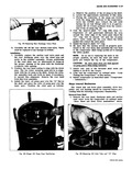 |
43 Removing Rear Discharge Valve Plate 8 Carefully lift off the rear suction reed valve Valv must be replaced if any damage is evident Installation 1 Carefully replace the suction reed valve plate |