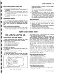
horn button or wiring is at fault ground the S terminal of the relay see Figure 8 120 for terminal location If the horn blows the horn button or wiring is at fault
| Book | Page | Context |
|---|---|---|
|
|
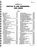
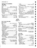
Seats 10 119 Cleaning of Upholstery 10 119 Front Seat Assembly Single Type Drivers Seat 10 120 Seat Back Replacement 10 120 Seat Replacement 10 120 Adjustment 10 121 Full Front Seat 10 121 Rear |
|
|
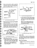
trouble connect a jumper lead to the H and B terminals of the relay see Figure 8 120 5 H i I B Fig 8 120 Horn Relay Terminals move the old cable by pulling ... horn button or wiring is at fault ground the S terminal of the relay see Figure 8 120 for terminal location If the horn blows the horn button or wiring is at fault |
|
|
1Ar20 5e i05 120 u 12 60 110 13S 150 9 6 18 65 120 150 16S r I1 8 140 170 200 Yr18 |
|
|
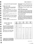
Length primary shoe 7 85 Length secondary shoe 9 42 Method of attachment Bonded Total effective area 120 8 sq in Master Cylinder Filler location On brace under dash fill from luggage compartment through access |
|
|
clearance to the striker inner face This adjustment can be made by using the 060 and 120 spacers as required fig 10 39a O6 OR 12 SPACERS AS REQUIRED LOCK ROTOR BODY LOCK HOUSING PILLAR |
|
|
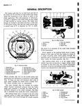
reverse motion The brake shoe facings are bonded to the shoes and have a total area of 120 square inches The cast iron brake drums have a contact area of 9 in diameter |