| Book |
Page |
Context |
 |
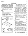 |
along each side roof inner rail including rear quarter windows as shown in View A Figure 10 111 4 Carefully remove tacks or staples securing headlining at windshield opening as shown in View ...
along back body opening as shown in View C Figure 10 111 then carefully detach cemented edges of headlining from openings 5 Working from front to rear of body disengage headlining 1 listing wire from ...
keep headlining clean 6 At roof bow bend down metal tabs shown in View D Fig 10 111 and remove listing support wire from roof bow 7 Disengage remaining listing wires from clips on side |
 |
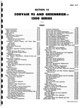 |
Side Intermediate Door Upper and Lower Rod Assembly 10 110 Side Rear Door Lock Assembly 10 111 Side Rear Door Window Assembly 10 111 Rear Doors 10 111 Rear Door Lock 10 112 Right Rear |
 |
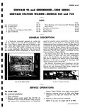 |
engine is available for the Lakewood Station Wagon Models An engine access door fig 6A 111 affords access to the engine oil filler tube and other components such as the distributor coil generator ...
Corvair 95 and Greenbrier 1200 Series except for Service Operations outlined below W Fig 6A 111 Engine Access Door PERATIONS Station Wagon Models raise engine access panel 3 Remove retaining bolt at oil filler tube |
 |
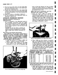 |
111 126 5 080 005 127 142 6 096 006 143 155 7 112 007 If initial indicator reading is below 025 replace thrust washer at the clutch hub front pump with OSO thrust washer |
 |
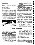 |
stock Inner cup tool should be 23 ls long and outer cup tool should be 111 18 long Replace outer cups with J 8849 and inner cups with J 8850 3 When installing |
 |
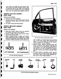 |
CYLINDER CYLINDER CYLINDER UNDER CAP SPRINGS CAP HOUSING A 111 |
 |
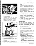 |
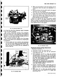
111 WASHER PLASTIC CAP OVER VACUUM PORT LEFT CARBURETOR NUT WASHER WASHER Fig 9 16 Removing Carburetor 2 Remove fuel inlet nut and gasket and remove filter element and spring 3 Remove six remaining bowl |
 |
 |
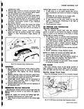
with serrations on rod held firmly against the pedal bracket Rotate the rod until a dimension of 111 18 is ob tained between the bench and the underside of the pin fig 9 5 PEDAL |
 |
 |
consists of two remotely located ENGINE TE i EMATURE v ENDING UNIT IL PRESSURE SENDING UNIT Fig 111 1117 00 Pressure and Cylinder Head Temperature Senders |
 |
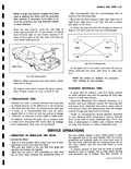 |
NOTE If large size balance weights have been 111 used to balance the wheel and tire assembly their removal is necessary to be able to re move the accessory trim ring Reinstall weights in same |
 |
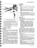 |
111 i Fig 8 58 Checking Breoker Arm Spring Tension 5 Place contact point assembly in position ovei pivot post and install hold down screws 6 Insert wire leads into position and tighten primary terminal |
 |
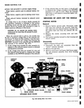 |
solenoid CONTACT FINGER GROMMET BUSHING m BRUSH INSULATED BRUSH F BRUSH SPRING GROUNDED BRUSH HOLDER Fig 111 3111 Start 3 If the solenoid does not feel warm it should pull in whenever the voltage available |
 |
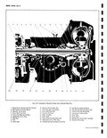 |
111 a old I 2 6 25 24 23 22 21 20 Fig 6C 2 Automatic Transmis 1 Planet Carrier Hub Transmission Output 10 Selective Pinior 2 Rear Selective End Play Spacers 11 Pinion Rear |
 |
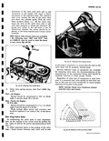 |
Turbo Air Engine H P O 649 Spring should be compressed to 111 1 g at which Leight it should check 71 to 81 lbs Weak springs affect power and economy and hould be replaced |
 |
 |
Lifting Corvair with Drive on Hoist 1 7 Standard Torque Table 1 7 i g fea 111 F D A ihicle Dimensions F Height Overall loaded 4 Door Station Wagon 33 3 All Other Models |
 |
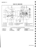 |
MILES 0 EVERY 25000 MILES CL Chassis LO EVERY 5000 MILES 11 m 3 r I I 111 |
 |
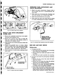 |
pushes plunger into switch body The distance between switch and tang on striker should be fig 8 111 5 Check operation of switch before replacing tunnel front cover i J v TRANSMISSION CONTROL ROD PART |
 |
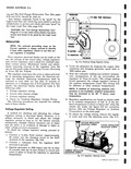 |
Light Load Test See page 8 2 CAUTION The Full Charge Hydrometer Test Page 8 111 is not valid unless battery has been tested and found to be good by the Light Load Test REGULATOR |
 |
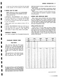 |
locations ar located differently and are covered in the Corvair 9l s portion of this section 11 111 corn GM 290 GM Y90 GM J00 ado tow Carb |


