| Book |
Page |
Context |
 |
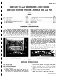 |
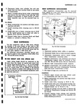
Corvair Sedan and Coupes The engine is located and mounted in 1 ie rear underbody fig 6A 110 The Corvair 95 and Greenbrier Series incorporates an engine access r 1 Fig 6A 110 Engine Location ...
FILLER TUBE Rer ioval and Installation 1 Drain crankcase 2 Remove engine access panel fig 6A 110 on Greenbrier and Corvair 95 Models Open tail gate and remove four retaining screws on Lakewood ENBRIER 1Z00 |
|
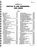 |
Cylinder 10 108 Side Intermediate Door Remote Control 10 108 Side Intermediate Door Lock Operating Lever 10 110 Side Intermediate Door Lock Assembly 10 110 Side Intermediate Door Upper and Lower Rod Assembly 10 110 |
|
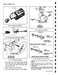 |
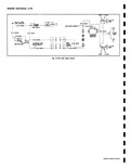
NUDE Fig 8 107 Stoplight Switch Installation back open end of the contact block A Fig 8 110 Then pull nylon contact block out until front of contact block lines up with the scribe mark ...
110 5 Install connector s onto new switch 6 Place switch plunger onto pin or range selector LT GREEN LT RUE TAN v WHEEL HOUSING ASSY a v EXISTINIG WELD NUTS SEALER APPLIED TO HOLES |
|
 |
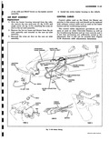
into position and align mount ing holes with drift 2 Install mounting bolts torquing nuts to 100 110 ft lbs 3 Install idler arm to frame torquing nuts to 13 22 ft lbs Install pitman ...
body supports in position Torque to 55 70 ft lbs Torque support to body nut to 70 110 ft lbs 5 Connect all linkage removed Refer to Section 6D and 6E for Transmission Linkage |
|
 |
None 047 062 1 016 001 063 078 2 032 002 079 094 3 048 003 095 110 |
|
 |
1Ar20 5e i05 120 u 12 60 110 13S 150 9 6 18 65 120 150 16S r I1 8 140 170 200 Yr18 |
|
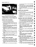 |
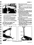
SAFETY SWITCH REPLACEMENT 1 Remove the retainer from pin on the transmission range selector assembly fig 8 110 2 Remove the two screws that attach the switch to the range selector assembly 3 Lower |
|
 |
BLACK Fig 156 1 VIOLET LT BLUE R N TAIL 20 GA BLACK LAMP REAR WIRING HARNESS 110 GA BLACK 20 CA BLACK LICENSE GENERATOR LAMPS U REGULATOR MAIN 10 GA BLACK WIRING HARNESS |
|
 |
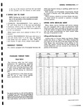
that it will not be covered here Figure 11 39 illustrates cable adjustments dimensions INLET B ASSY 110 WIRE 4CK 8 GRAY i ll v y ONHEATER CONTROL I HARNESS I LAMP CONNECTION GRAY CONTROL |
|
 |
834S 3 J S888 3 1 Ypw CieMl Am Wddw e COf1VAIR 110 |
|
 |
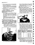
NOTE The cooler tempering air will maintain a temperature of about 110 F during normal vehicle operation while the heated air entering the heater housing may reach 160 F The tempered air then flows through |
|
 |
spans the distance between the driver s compartment and the front of the transmission At the r 110 AND 900 SERIES TRANSMISSION IDEX Page Disassembly of Mainshaft 6D 19 Inspection and Repair 6D 20 Transmission |