Jeep Parts Wiki | Ford Parts Wiki
Home | Search | Browse
|
Body Service Manual August 1964 |
|
Prev
 Next
Next
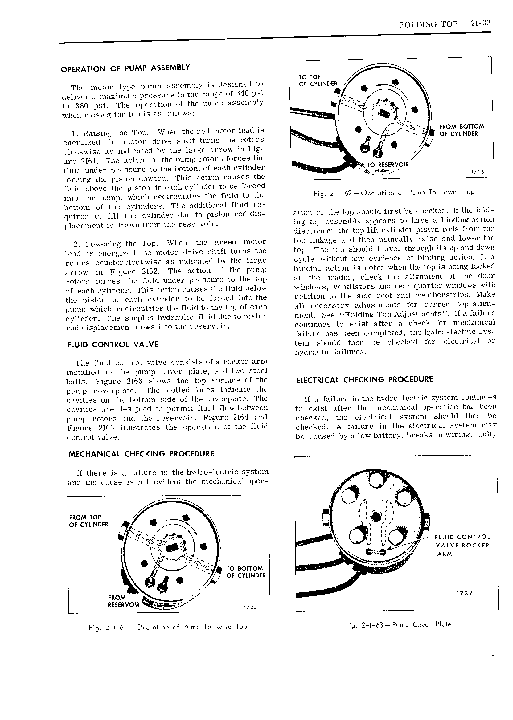
OPERATION OF PUMP ASSEMBLY Fi 77 77744 TO T0 The motor tvpe pump assembly is designed to Op cytinpen Q dehvei a m i nmuni pi essui e in the range of 3 psi b to 380 psi The operation of the pump assembly 1 Joy when raising the top is as follows i l Raising the Top When the red motor lead is Q ff L C FROM BOTTOM energized the motor drive shaft turns the rotors OF CVUNDFR l clockwise as indicated by the large arrow in Fig 6 ure 2161 The action of the pump rotors forces the v I fluid under pressure to the bottom of each cylinder Y TO KEERVOIR i forcing the piston upward This action causes the 7 L fluid above the piston in each cylinder to be forced into the pump which recirculates the fluid to the Fig 2 i 62 Opei ti n of Pump To Lower Tmp bottom ot the cylinders The additional fluid re quired to fill the cylinder due to piston rod dis ation of the top should first be checked lf the fold placement is drawn from the reservoir ing top assembly appears to have a binding action disconnect the top lift cylinder piston rods from the 2 Lowering the Top When the green motor top linkage and then manually raise and lower the lead is energized the motor drive shaft turns the top The top should travel through its up and down rotors countercluckwise as indicated by the large cycle without any evidence of binding action lf a arrow in Figure 2162 The action of the pump binding action is noted when the top is being locked rotors forces the fluid under pressure to the top at the header check the alignment of the door of each cylinder This action causes the fluid below windows ventilators and rear quarter windows with the piston in each cylinder to be forced into the relation to the side roof rail weatherstrips Make pump which recirculates the fluid to the top of each all necessary adjustments for correct top align eylinder The surplus hydraulic fluid due to piston ment See F0lding Top Adjustments lf a failure rod displacement flows intothe reservoir continues to exist after a check for mechanical failure has been completed the hydro lectric sys FLUID CONTROL VALVE tem should then be checked for electrical or hydraulic failures The fluid control valve consists of a rocker arm installed in the pump cover plate and two steel balls Figure 2163 shows the top surface ofthe EC R CA CHECMNG pROCEDURE pump coverplate The dotted lines indicate the C VltIE S UH th I Jtt n Side ef the W l7li t Th lf a failure in the hydro lectric system continues V S are desleried te peruiit fluid i1 WL PtW to exist mei me meeimieai iipemnmi has been 1 i 1 i S wd the reS v ir Fieure 2164 wd ieiieekea me eiemaui system shouia then be Ffwri mv 11 St teS the 1 c ti ef the fluid checked A mime in the eieewioai system may control valve be caused by a low battery breaks in wiring faulty MECHANICAL CHECKING PROCEDURE lf there is a failure in the hydro lectric system and the cause is not evident the mechanical oper l mom TOP F I orcvirunsn OA il f Z C ek i i Q y GI r mum comuoi a ii i V jr vALvE izocxzn i E C i Ar y L V C J ARM C 9 TO BOTTOM or CYLINDER 6 O 1 i mom e 1732 RESERv0m dg V 5 i Fig 2 l 6i Opei ii ii ot Pump To Raise Top Fig 2 l s3 Piimp Cai ei Piqie