Jeep Parts Wiki | Ford Parts Wiki
Home | Search | Browse | Marketplace | Messages | FAQ | Guest
|
Body Service Manual August 1964 |
|
Prev

 Next
Next
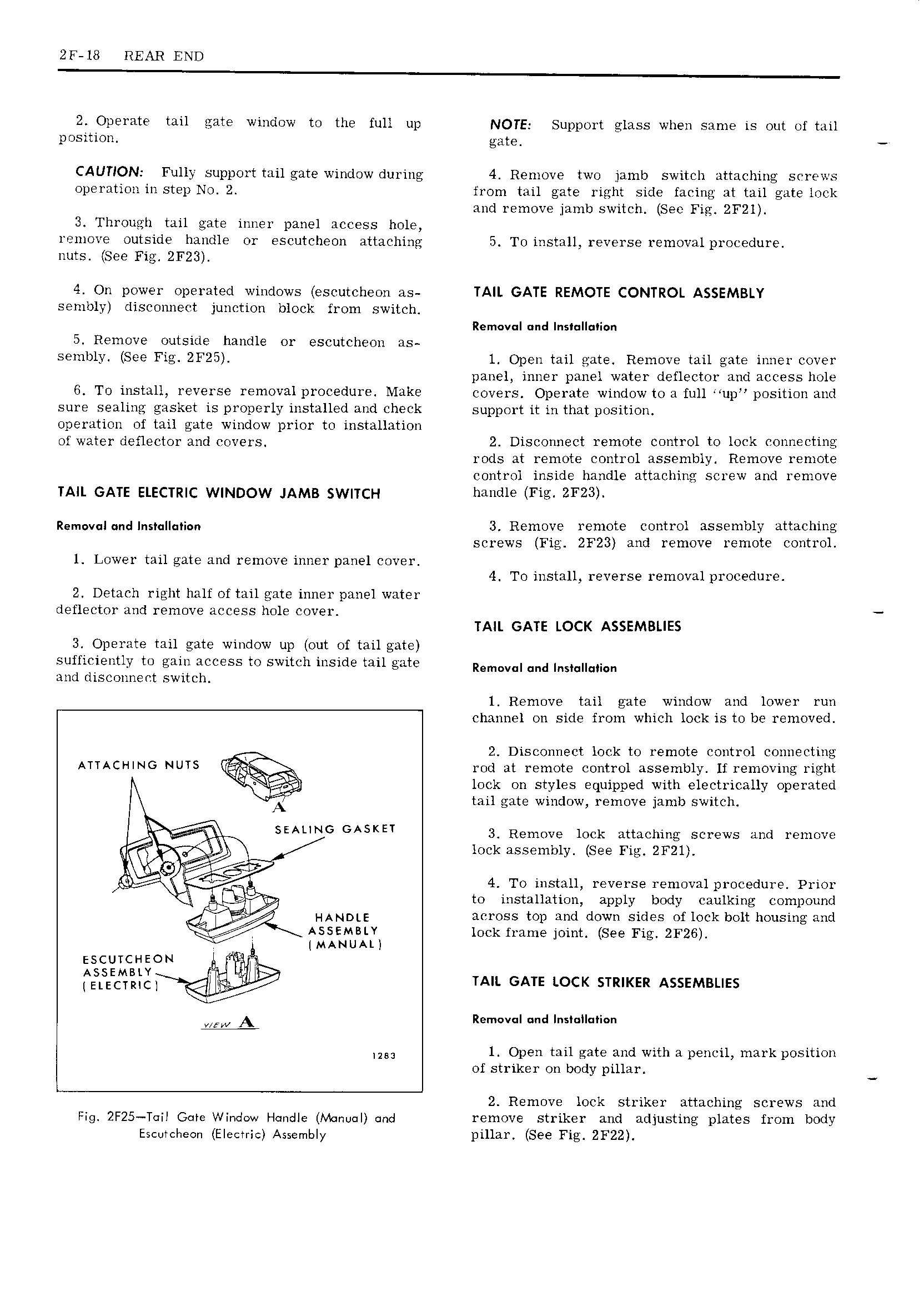
2F 18 REAR END 2 Operate tail gate window to the full up NOTE Support glass when same is out of tail position goto CAUTION Fully support tail gate window during 4 Remove two jamb switch attaching screws operation in step No 2 from tail gate right side facing at tail gate lock and remove jamb switch Sec Fig 2F2l 3 Through tail gate inner panel access hole remove outside handle or escutcheon attaching 5 To install reverse removal procedure nuts See 2F23 4 On power operated windows escutcheon as TAIL GATE REMOTE CONTROL ASSEMBLY sembly disconnect junction block from switch Removal und Ins Ii n 5 Remove outside handle or escutcheon as senihly See 2F25 1 Open tail gate Remove tail gate inner cover panel inner panel water deflector and access hole 6 To install reverse removal procedure Make covers Operate window to a full up position and sure sealing gasket is properly installed and check support it in that position operation of tail gate window prior to installation of water deflector and covers 2 Disconnect remote control to lock connecting rods at remote control assembly Remove remote control inside handle attaching screw and remove TAIL GATE ELECTRIC WINDOW JAMB SWITCH handle Fig ZF23 Rem v I ndlns II i n 3 Remove remote control assembly attaching screws Fig ZF23 and remove remote control 1 Lower tail gate and remove inner panel cover 4 To install reverse removal procedure 2 Detach right half of tail gate inner panel water deflector and remove access hole cover TAIL GATE LOCK ASSEMBLIES 3 Operate tail gate window up out of tailgate sufficiently to gain access to switch inside tail gate Removal and ns n and disconnect switch 1 Remove tail gate window and lower run channel on side from which lock is to be removed 2 Disconnect lock to remote control connecting ATTACHING NUTS rod at remote control assembly If removing right lock on styles equipped with electrically operated tail gate window remove jamb switch N if SEAUNG GASKET 3 Remove lock attaching screws and remove lock assembly See Fig 2F2l QZ 4 To install reverse removal procedure Prior e to installation apply body caulking compound HANDLE across top and down sides of lock bolt housing and a y ASSEMBLY lock frame joint See Fig 2F26 MANUAL escutcneow I ESLSeEcNt dg jig TAIL GATE LOCK STRIKER ASSEMBLIES x2 ww A Removqn und Insiannaiaim 83 1 Open tail gate and with a pencil mark position of striker on body pillar 2 Remove lock striker attaching screws and Fig 2F25 T iI Gate Window Handle Nbnoul cmd remove striker and adjusting plates from body Escutcheon Electric Assembly pillar See Fig 2F22

 Next
Next