Jeep Parts Wiki | Ford Parts Wiki
Home | Search | Browse
|
Body Service Manual August 1964 |
|
Prev
 Next
Next
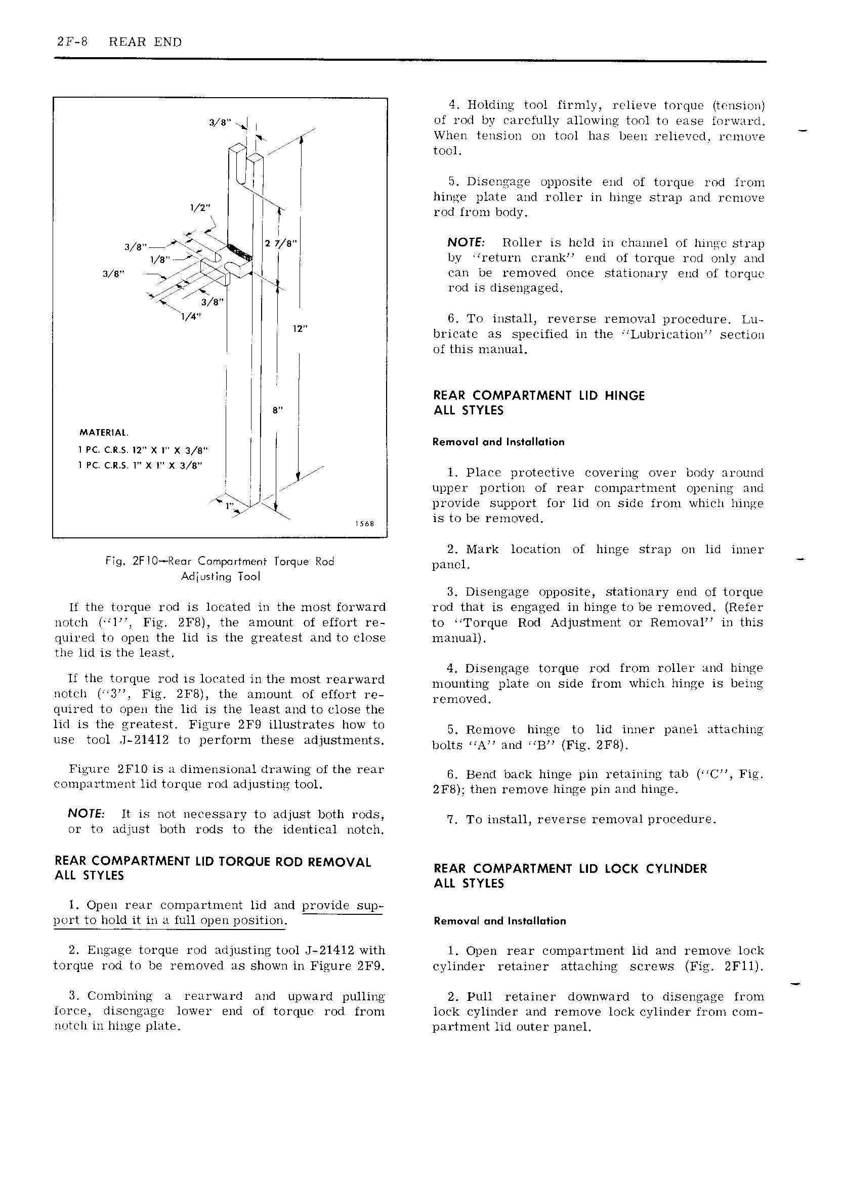
2F 8 REAR END 4 Holding tool firmly relieve torque tmisirm 3 8 J of rod by carefully allowing tool to ease lorward 1 I When tension on tool has been relieved rrunore tool 5 Disongage opposite end of torque rod from hinge plate and roller in Innge strap and rruiiove I 2 I j rod from body e I 3 F7 r 2 7 s NOTE Roller is held in channel of hinge strap 1 8 rkjw I y return crank end of torque rod only and 2 sr i x f j I can be removed once stationary end of torque 5 R rod disengaged s s I H 6 To install reverse removal procedure Lu IZ bricate specified inthe LuI1rication section of this manual r REAR COMPARTMENT LID HINGE e ALL STYLES MATERIAL A 1 PC CRS IT X X 3 B Rem v I and lns II i n I PC C R S IR X In X 3 BR l Place protective covering over body around Q I upper portion of rear compartment opening and j ri I provide support for lid on side from which hinge VMS is to be removed 2 Mark location of hinge strap on lid inner Fig 2FIO Re r Compartment Torque Rod DQHCL Adjusting Tool 3 Disengage opposite stationary end of torque It the torque rod is located in the most forward rod that is engaged in hinge to be removed Refer notch I l Fig ZF8 the amount of effort re to Torque Rod Adjustment or Removal in this quired to open the lid is the greatest and to close manual the lid is the least 4 Disengage torque rod from roller and hinge H OIR t q O md1S1 t t e m R St OR m d mounting plate on side from which hinge is being notch 3 Fig 2FB the amount of effort re 1 mOv I R quired to open the lid is the least and to close the lid is the greatest Figure 2F9 illustrates how to 5 Rpmgvc himc to Hd imwr panel utwcjlim use tool J 21412 to perform these adjustments bims NAM and MBL Fig 2F8 R Figure 2FlO is a dimensional drawing ofthe rear GV Bend back hinge pm remilmm mb MCM coinpartment lid torque rod adjusting tool 2F8 than remove Hinge pm and jm g9 A R NOTE It is not necessary to adjust both rods 7 TO hmmm revers removal m OC9dm or to adjust both rods to the identical notch J REAR MP ALL 5 ARTMENT LID TOROUE ROD REMOVAL REAR c0MPARrMENr uu iczcx cvur mER ALL STYLES l Open rear compartment lid and provide sup port to hold it in ri full open position Removul und Installation 2 Engage torque rod adjusting tool J 2l4l2 with 1 Open rear compartment lid and remove lock torque rod tn be removed as shown in Figure 2F9 cylinder retainer attaching screws Fig 2Fll 3 Combining a rearward and upward pulling 2 Pull retainer downward to disengage from force disengago lower end of torque rod from lock cylinder and remove lock cylinder from com notcli in hinge plate partment lid outer panel