Jeep Parts Wiki | Ford Parts Wiki
Home | Search | Browse | Marketplace | Messages | FAQ | Guest
|
Body Service Manual August 1964 |
|
Prev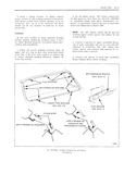
 Next
Next
4410043
4410043
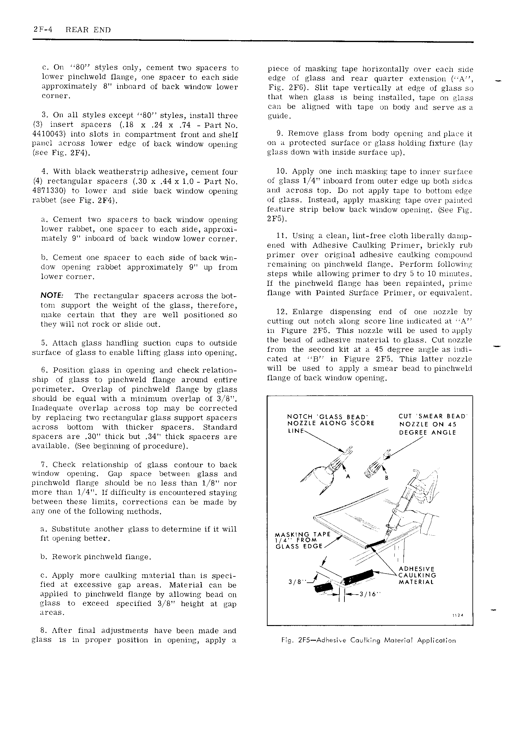
2F 4 REAR END c On 80 styles only cement two spacers to piece of masking tape horizontally over each side lower pinchweld flange one spacer to each side edge of glass and rear quarter extension approximately B inboard of back window lower Fig ZF6 Slit tape vertically at edge of glass so corner that when glass is being installed tape on glass can be aligned with tape on body and serve as a 3 On all styles except 80 styles install three guide 3 insert spacers 18 x 24 x 74 Part No 4410043 into slots in compartment front and shelf 9 R mgv EJIHSS f1 m bOdY FC i ii 1 it ngnnn ncynss lnwer Qdgn ng back Window Opening on 4 protected surface or glass holding fixture lay gpg Fig gF4 glass down with inside surface up 4 With black weatherstrip adhesive cement four 10 ADDIY OM inch Uiilskms D W UWB S 1 ii 4 rectangular spacers 30 X 44 x 1 0 Part No of glass l i 4 inboard from outer edge up both sidts itmsso m itgtwer und side back window opening and across tap Du i t apply tape to bwttciii ease ynbbgt gpg Fig 2F4 of glass Instead apply masking tape over painted feature strip below back window opening See Fig a Cement two spacers to back window opening 2F5 lower rabbet one spacer to each side approxi mately 9 inboard of back window lower corner 11 Using H 1 a 1mt h E mth mwmuy damp ened with Adhesive Caulking Primer brickly rub n Cement nne Snnner tn mph Side nf bank w n primer over original adhesive caulking conipnnnti dow opening rabbet apprqXim it v gv up fl nn 1 111l1i1 iHt un piuchweld flange Perform following wwe Cm n Q steps while allowing primer to dry 5 to 10 mniutes If the pinchweld flange has been repainted prime NOTE The wcnmgulm spacers nC1 OSSth bOt flange with Painted Surface Primer or equivalent toni support the weight of the glass therefore make certain that they are well positioned so l2 Enlarge dlspensmg Eud ef nge UOZZIE by thy Win nm 1 OCk O1 Sung Out cutting out notch along score line indicated at A in Figure ZF5 This nozzle will be used to apply s inmuu uiuss handling suction uupu to outside the bm ef Muiesire e i 1 e1 SS Cut i ZZk surface of glass to enable lifting glass into opening hmm tht SQCOUQ kxt at H 45 degr Anglia BS mm cated at B in Figure 2F5 This latter nozzle pnsnwn glass in npening and Check 1 Ek tiOn will be used to apply a smear bead to pinchweld ship of glass to pinchweld flange around entire Hull f kWi 1 W 1 i a perimeter Overlap of pinchweld flange by glass should be equal with a minimum overlap of 3 8 Inadequate overlap across top may be corrected by replacing two rectangular glass support spacers NOTCH GLASS BEAD CUT SMEAR BEAD V 1 NOZZLE ALONG SCORE NOZZLE ON 45 across bottom with thicker spacers standard UNE DEGREE ANGLE spacers are 30 thick but 34 thick spacers are available See beginning of procedure it 7 Check relationship of glass contour to back r window opening Gap space between glass and A B pinchweld flange should be no less than 1 8 nor H G more than 1 4 If difficulty is encountered staying if between these limits corrections can be made by g 1 if EMM any one ofthe following methods I L V i i Substitute another glass to determine if it will MASMNG TAPE A tit opening better 1 4 FROM GLASS EDGE I t b Rework pinchweld flange I I ADHESIVE c Apply more caulking material than is speci CAULKING lied at excessive gap areas Material can be 3 8 MATERIAL applied to pinchweld flange by allowing bead on 3 T6 glass to exceed specified 3 B height at gap areas mi 8 After final adjustments have been made and glass is in proper position in opening apply a Fig 2F5 Ad e i ve Cuulking Material Application