Jeep Parts Wiki | Ford Parts Wiki
Home | Search | Browse | Marketplace | Messages | FAQ | Guest
Prev
 Next
Next
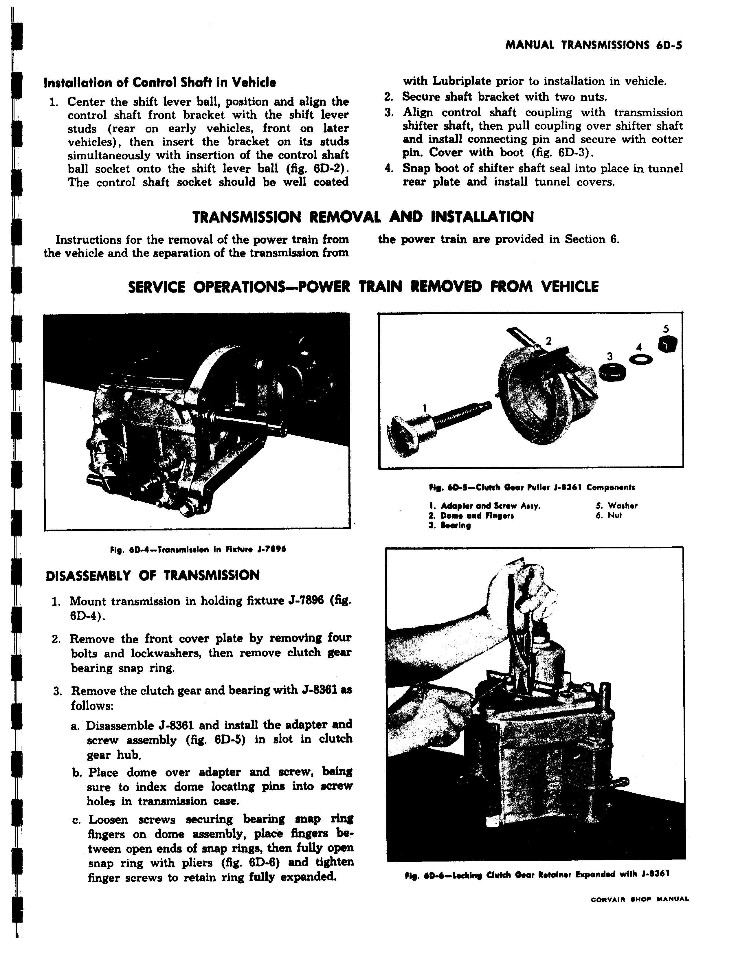
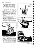
Installation of Control Shaft in Vehicle 1 Center the shift lever ball position and align the control shaft front bracket with the shift lever studs rear on early vehicles front on later vehicles then insert the bracket on its studs simultaneously with insertion of the control shaft ball socket onto the shift lever ball fig 6D 2 The control shaft socket should be well coated TRANSMISSION REMO Instructions for the removal of the power train from the vehicle and the separation of the transmission from SERVICE OPERATIONS POWER K I S 7 Fig 6D 4 Transmission In Fixture J 7696 DISASSEMBLY OF TRANSMISSION 1 Mount transmission in holding fixture J 896 fig 6D 4 2 Remove the front cover plate by removing four bolts and lockwashers then remove clutch gear bearing snap ring 3 Remove the clutch gear and bearing with J 8381 as follows a Disassemble J 8361 and install the adapter and screw assembly fig 6D 5 in slot in clutch gear hub b Place dome over adapter and screw being sure to index dome locating pins into screw holes in transmission case c Loosen screws securing bearing snap AN fingers on dome assembly place fingers between open ends of snap rings then fully oper snap ring with pliers fig 6D 8 and tighter finger screws to retain ring fully expanded with Lubriplate prior to installation in vehicle 2 Secure shaft bracket with two nuts 3 Align control shaft coupling with transmission shifter shaft then pull coupling over shifter shaft and install connecting pin and secure with cotter pin Cover with boot fig 6D 3 4 Snap boot of shifter shaft seal into place in tunnel rear plate and install tunnel covers VAL AND INSTALLATION the power train are provided in Section 6 TRAIN REMOVED FROM VEHICLE s d p O f Fig D S Clwch Gear PuIlor J 361 Components 1 Adapter and Screw Assy 5 washer 2 Dom and Fingers 6 Nut 3 Bearing flh r w a y v Mg 604 Locking CIrMch Gear Retainer Expanded with J 361 nnWW iYlf MANUAL