Jeep Parts Wiki | Ford Parts Wiki
Home | Search | Browse | Marketplace | Messages | FAQ | Guest
Prev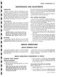
 Next
Next
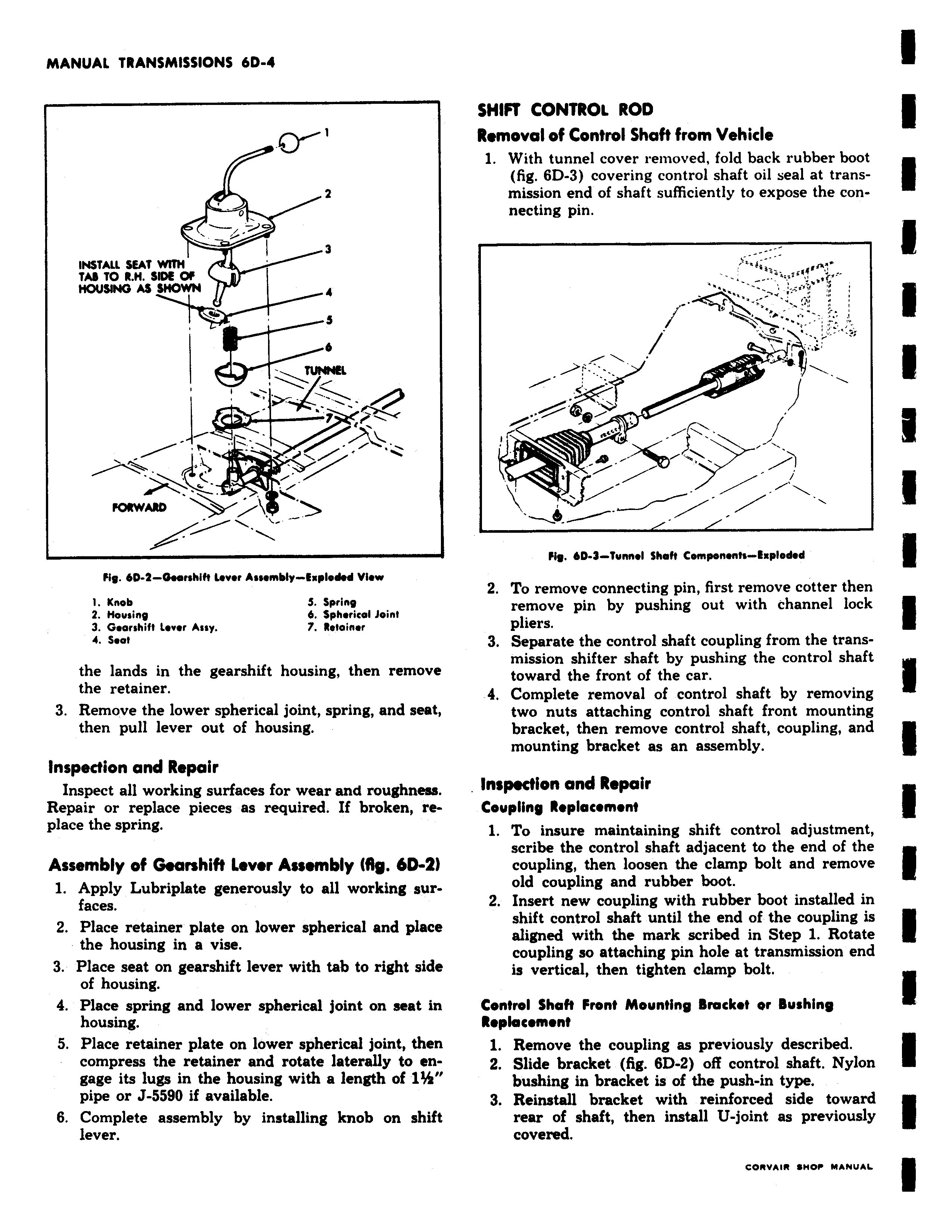
2 o 3 INSTALL SEAT WITM TAB TO R M SR E Of HOUSING AS SMOWN 6 TUNNEL Fig FORWARD 6D 4 Geenhih Lower Assembly Exploded view 1 Knob 5 Spring 2 Mousing 6 Spherical Joint 3 Gearshift Lever Assy 7 Retainer Seat the lands in the gearshift housing then remove the retainer 3 Remove the lower spherical joint spring and seat then pull lever out of housing Inspection and Repair Inspect all working surfaces for wear and roughness Repair or replace pieces as required If broken replace the spring Assembly of Gearshift Lever Assembly IAR 6D Z 1 Apply Lubriplate generously to all working surfaces 2 Place retainer plate on lower spherical and place the housing in a vise 3 Place seat on gearshift lever with tab to right side of housing 4 Place spring and lower spherical joint on seat in housing 5 Place retainer plate on lower spherical joint then compress the retainer and rotate laterally to engage its lugs in the housing with a length of l pipe or J 5590 if available 6 Complete assembly by installing knob on shift lever SHIFT CONTROL ROD Removal of Control Shaft from Vehicle 1 With tunnel cover removed fold back rubber boot fig 6D 3 covering control shaft oil seal at transmission end of shaft sufficiently to expose the connecting pin aN 6 1 i w Fig AD 9 Tunnel Shah Components Exploded 2 To remove connecting pin first remove cotter then remove pin by pushing out with channel lock pliers 3 Separate the control shaft coupling from the transmission shifter shaft by pushing the control shaft toward the front of the car 4 Complete removal of control shaft by removing two nuts attaching control shaft front mounting bracket then remove control shaft coupling and mounting bracket as an assembly Inspection and Repair Coupling Replacement 1 To insure maintaining shift control adjustment scribe the control shaft adjacent to the end of the coupling then loosen the clamp bolt and remove old coupling and rubber boot 2 Insert new coupling with rubber boot installed in shift control shaft until the end of the coupling is aligned with the mark scribed in Step 1 Rotate coupling so attaching pin hole at transmission end is vertical then tighten clamp bolt Control Shah Front Mounting Bracket or Bushing Replacement 1 Remove the coupling as previously described 2 Slide bracket fig 6D 2 off control shaft Nylon bushing in bracket is of the push in type 3 Reinstall bracket with reinforced side toward rear of shaft then install U joint as previously covered