Jeep Parts Wiki | Ford Parts Wiki
Home | Search | Browse
|
Body Service Manual August 1964 |
|
Prev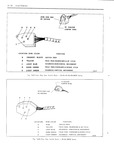
 Next
Next
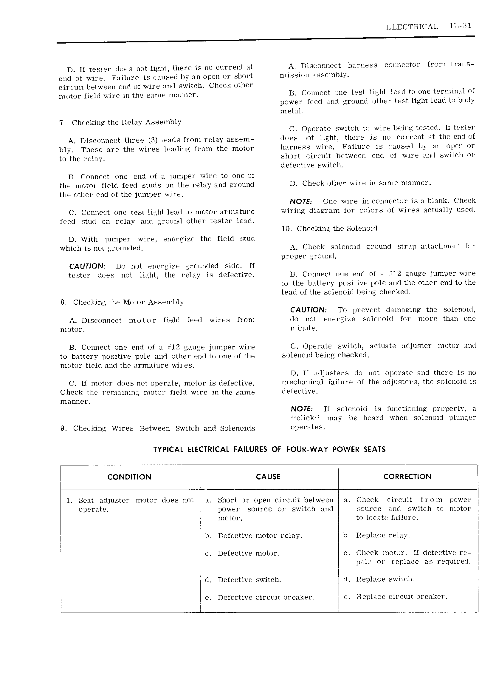
ELECTRICAL lL 3l D If tester does not light there is no current at A Disconnect harness eonnm tor ron trans end of wire Failure is caused by an open or short mission assembly circuit between end of wire and switch Cheek other motor field wire in the same manner B Connect one test light lead to one terminal of power feed and ground other test light lead to body metal 7 Checking the Relay Assembly C Operate switch to wire being tested lf tester A Disconnect three 3 l ilClS from relay assem does not light there is no current at the end of bly These are the wires leading from the motor harness wire Failure is caused by an open or to the relay short circuit between end of wire and switch or C defective switch B Connect one end of a jumper wire to one of the motor field feed studs on the relay and ground D Check other wire in same manner the other end of the jumper wire NOTE One wire in connector is a blank Check C Connect one test light lead to motor armature wiring diagram for colors of wires actually used feed stud on relay and ground other tester lead 10 Checking the Solenoid D With jumper wire energize the field stud which is not grounded A Check solenoid ground strap attachment for proper ground CAUTION Do not energize grounded side If tester does not light the relay is defective B Connect one end of a 12 gauge jumper wire to the battery positive pole and the other end to the lead of the solenoid being checked 8 Checking the Motor Assembly CAUTION To prevent damaging the solenoid A Disconnect motor field feed wires from do not energize solenoid for more than one motor minute B Connect one end of a H2 gauge jumper wire C Operate switch actuate adjuster motor and to battery positive pole and other end to one of the S Z l ll0l l twill llP k l motor field and the armature wires D If adjusters do not operate and there is no C If motor does not operate motor is defective ineelianical failure of the adjusters the solenoid is Check the remaining motor field wire inthe same l f9CtlV manner NOTE If solenoid is functioning properly a click may be heard when solenoid plunger 9 Checking Wires Between Switch and Solenoids Operates TYPICAL ELECTRICAL FAILURES OF FOUR WAY POWER SEATS CONDITION CAUSE CORRECTION I l Seat adjuster motor does not a Short or open circuit between a Check circuit from power operate power source or switch and source and switch to motor motor to locate failure I I b Defective motor relay b Replace relay l c Defective motor c Check motor If defective re l pair or replace as required I d Defective switch d Replace switch I r e Defective circuit breaker j Replace circuit breaker l mmm l