Jeep Parts Wiki | Ford Parts Wiki
Home | Search | Browse | Marketplace | Messages | FAQ | Guest
|
Body Service Manual August 1964 |
|
Prev
 Next
Next
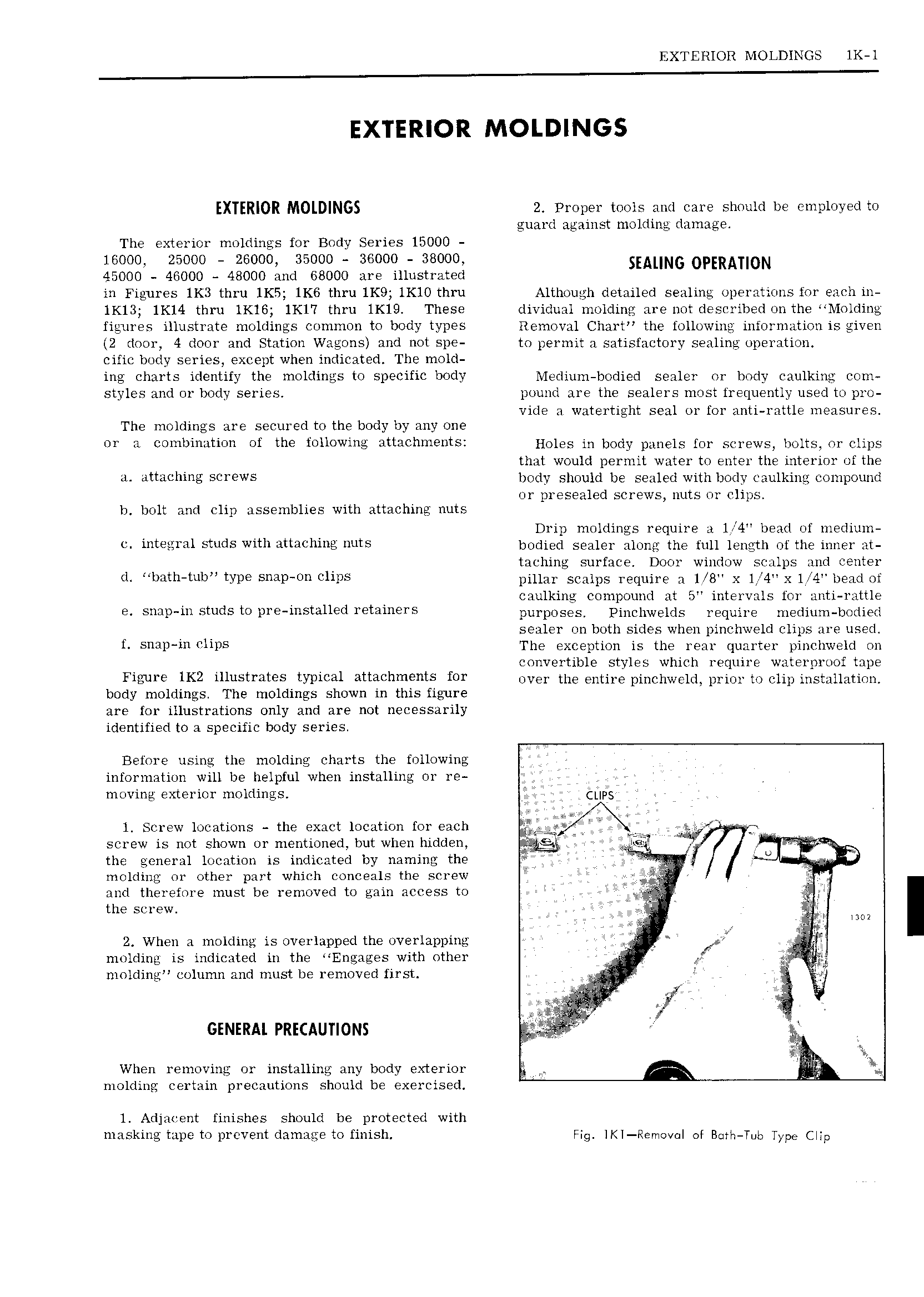
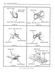
EXTERIOR MOLDINGS 1K l EXTERIOR MOLDINGS EXTERIOR MOLDINGS 2 Proper tools and care should be employed to guard against molding damage The exterior moldings for Body Series 15000 16000 25000 26000 35000 36000 38000 45000 46000 48000 and 68000 are illustrated in Figures 1K3 thru 1K5 1K6 thru lK9 lKl0 thru Although detailed sealing operations for each in lK13 1K14 thru lKl6 1Kl 7 thru lK19 These dividual molding are not described on the Molding figures illustrate moldings common to body types Removal Chart the following information is given 2 door 4 door and Station Wagons and not spe to permit a satisfactory sealing operation cific l 0 lY series except when indicated The mold ing charts identify the moldings to specific body l iediu1n bodied sealer or body caulking com styles and or body series pound are the sealers most frequently used to pro vide a watertight seal or for anti rattle measures The moldings are secured to the body by any one or a combination of the following attziChHi htSI Holes in body panels for screws bolts or clips that would permit water to enter the interior of the a attaching screws body should be sealed with body caulking compound or presealed screws nuts or clips h bolt and clip assemblies with attaching nuts Drip moldings require a l 4 bead of medium c integral studs with attaching nuts bodied sealer along the full length of the inner at taching surface Door window scalps and center d bath tub type snap on clips pillar scalps require a 1 8 x 1 4 X 1i 4 bead of caulking compound at 5 intervals for anti rattle e snap in studs to pre installed retainers purposes Pinchwelds require medium bodied sealer on both sides when pinchweld clips are used f snap inclips The exception is the rear quarter pinchweld on convertible styles which require waterproof tape Figure lK2 illustrates typical att h 1 1 tS f01 over the entire pinchweld prior to clip installation body moldings The moldings shown in this figure are for illustrations only and are not necessarily identified to a specific body series Before using the molding charts the following information will be helpful when installing or re moving exterior moldings Cups l Screw locations the exact location for each g Q r r v n rj screw is not shown or mentioned but when hidden pkt the general location is indicated by naming the X i V molding or other part which conceals the screw if and therefore must be removed to gain access to A the screw p gy Mm 2 When a molding is overlapped the overlapping f i molding is indicated in the Engages with other T h Zif niolding column and must be removed first it N 1 i GENERAL PRECAUTIONS i 1 0 iz When removing or installing any body exterior Q molding certain precautions should be exercised l Adjacent finishes should be protected with masking tape to prevent damage to finish Fig IK Removal of Both Tub Type Clip