Jeep Parts Wiki | Ford Parts Wiki
Home | Search | Browse
|
Body Service Manual August 1964 |
|
Prev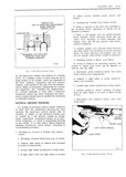
 Next
Next
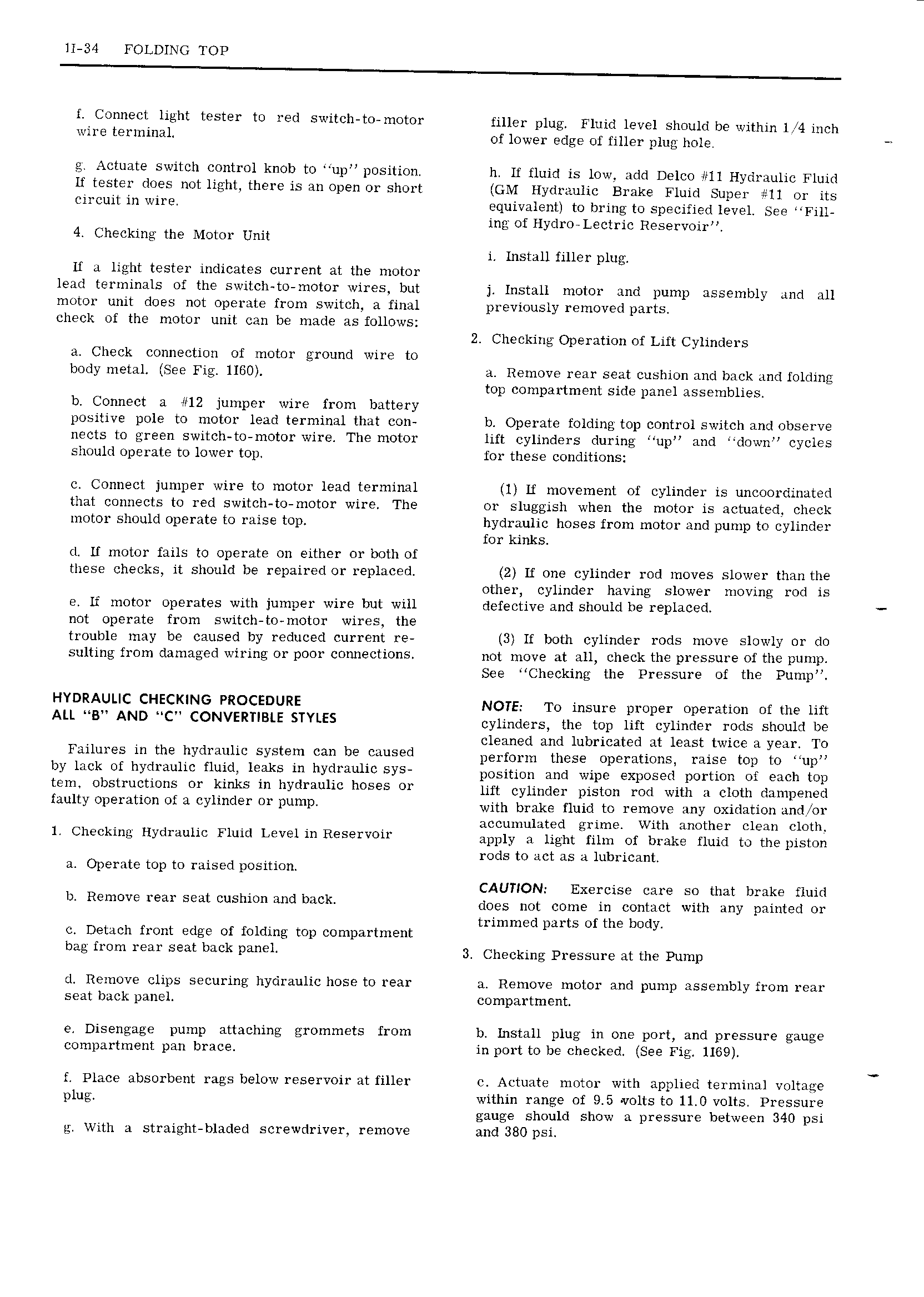
1I 34 FOLDING TOP f Connect light tester to red switch to motor filler plug Fluid level should be within 1 4 inch wire terminal of lower edge of filler plug hole Actuate switch control knob to up position h If fluid is low add Delco 11 Hydraulic Fluid If tester does not light there is an open or short GM Hydraulic Brake Fluid Super 11 or its circuit in wire equivalent to bring to specified level See Fill ing of Hydro Lectric Reservoir 4 Checking the Motor Unit i Install filler plug If a light tester indicates current at the motor lead terminals of the switch to motor wires but j Install motor and pump assembly and all motor unit does not operate from switch a final previously removed parts check of the motor unit can be made as follows 2 Checking Operation of Lift Cylinders a Check connection of motor ground wire to body metal See Fig 1160 a Remove rear seat cushion and back and folding top compartment side panel assemblies b Connect a 12 jumper wire from battery positive pole to motor lead terminal that con b Operate folding top control switch and observe nects to green switch to motor wire The motor lift cylinders during up and down cycles should operate to lower top for these conditions c Connect jumper wire to motor lead terminal 1 Lf movement of cylinder is uncoordinated that connects to red switch to motor wire The or sluggish when the motor is actuated check motor should operate to raise top hydraulic hoses from motor and pump to cylinder for kinks d Lf motor fails to operate on either or both of these checks it should be repaired or replaced 2 If one cylinder rod moves slower than the other cylinder having slower moving rod is e If motor operates with jumper wire but will defective and should be replaced not operate from switch to motor wires the trouble may be caused by reduced current re 3 If both cylinder rods move slowly or do sulting from damaged wiring or poor connections not move at all check the pressure of the pump See Checking the Pressure of the Pump HYDRAULIC CHECKING PROCEDURE NOTE To insure proper operation ofthe lift Au MBU AND MCH CONVERTIBLE STYLES cylinders the top lift cylinder rods should be cleaned and lubricated at least twice a year To Failures in the hydraulic system can be caused perform these Oppmtlmlsy False tcp to nupn by kick Of hydrsukc fluid leaks in hYd euhe sYs position and wipe exposed portion of each top tem ebstmetiens er kinks in 1 vdr hoses OY lift cylinder piston rod with a cloth dampened fault 0l emtiO ef 3 eykmler m Fume with brake fluid to remove any oxidation and or accumulated grime With another clean cloth 1 Checking Hydraulic Fluid Level in Reservoir apply ll light gllm Ol blpllg fluid to theplslpp rods to act as a lubricant a Operate top to raised position CAUTION Exercise care so that brake fluid b Remove rear Seat Cushion and beck does not come in contact with any painted or trimmed parts of the body c Detach front edge of folding top compartment bee fwm Year seat back Psnek 3 Checking Pressure at the Pump d Remove clips securing hydraulic hose to rear a Remove motor and pump assembly from rear seat back panel compartment e Disengage pump attaching grommets from b Install plug in one port and pressure gauge compartment pan brace in port to be checked See Fig 1169 f Place absorbent rags below reservoir at filler c Actuate motor with applied terminal voltage plug within range of 9 5 volts to 11 0 volts Pressure gauge should show a pressure between 340 psi g With a straight bladed screwdriver remove and 380 psi