Jeep Parts Wiki | Ford Parts Wiki
Home | Search | Browse
|
Body Service Manual August 1964 |
|
Prev
 Next
Next
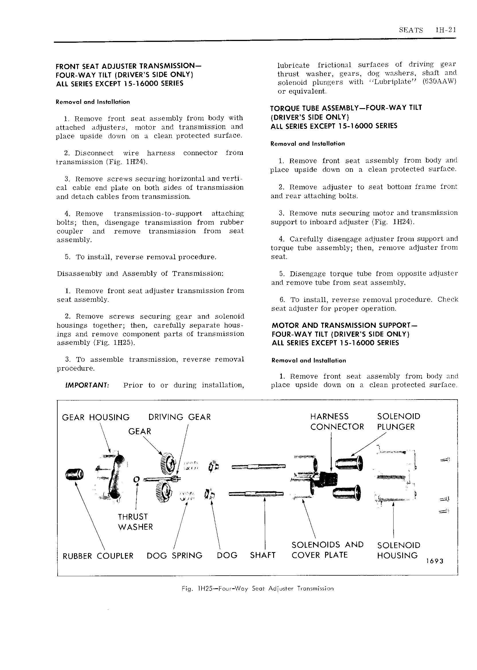
SEATS lH 2l I FRONT SEAT ADJUSTER TRANSMISSION lubricate frictional surfaces of driving gear FOUR WAY TILT DRIVERIS SIDE ONLY thrust washer gears dog washers shaft and ALL SERIES EXCEPT I5 16000 SERIES solenoid plungers with Lubriplate ISBOAAWI or equivalent Removul nd I s Il 1i n TORQUE TUBE ASSEMBLY FOUR WAY TILT 1 Remove front seat assembly from body with DRlVER S SIDE ONLY attached adjusters motor and transmission and ALL SERIES EXCEPT 5 I6000 SERIES place upside down on a clean protected surface Rem v I and InsI l lion 2 Disconnect wire harness connector from transmission Fig 1H24 1 Remove front seat assembly from body and place upside down on a clean protected surface 3 Remove screws securing horizontal and vertie cal cable end plate on both sides of transmission 2 Remove adjuster to seat bottom frame front and detach cables from transmission and rear attaching bolts 4 Remove transmission to support attaching 3 Remove nuts securing motor and transmission bolts then disengage transmission from rubber support to inboard adjuster Fig 1H24I coupler and remove transmission from seat assembly 4 Carefully clisengage adjuster from support and torque tube assembly then remove adjuster from 5 To install reverse removal procedure seat Disassembly and Assembly of Transmission 5 Disengage torque tube from opposite adjuster and remove tube from seat assembly 1 Remove front seat adjuster transmission from seat assembly 6 To install reverse removal procedure Check seat adjuster for proper operation 2 Remove screws securing gear and solenoid housings together then carefully separate h0us MOTOR AND TRANSMISSION SUPPORT ings and remove component parts of transmission FOUR WAY T LT DR VER DE ONLY assembly Fig 1H25I ALL SERIES EXCEPT I5 16000 SERIES 3 To assemble transmission reverse removal Removujundjnsjujjujicn procedure 1 Remove front seat assembly from body and IMPORTANT Prior to or during installation place upside down on zi clean protected surface GEAR HOUSING DRIVING GEAR HARNESS SOLENOID I GEAR CONNECTOR PLUNGER I 1 t I 4 ga t A I f g 5 Htl 3 e is I II K I 4 il katie A II Z Zkl I I I 5 nuzusr I I WASHER jI I t SOLENOIDS AND SOLENOID I RUBBER COUPLER DOG SPRING DOG SHAFT COVER PLATE HOUSING 1693 I Fig IH25 F nr W y Sem AdIosIer Ticnsmission