Jeep Parts Wiki | Ford Parts Wiki
Home | Search | Browse
|
Body Service Manual August 1964 |
|
Prev
 Next
Next
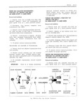
111 20 SEATS rtool remove shoulder screws securing 4 Disconnect drive cable from actuator ii age to vertical gearnut Fig 1H24 assembly Remove jackscrew down stop from jack 5 Remove screws securing horizontal actuator sciew Fig lH24 assembly to adjuster lower track then remove actuator from adjuster assembly Fig 1H24 5 Using a portable power source to energize k tliei motor actuate vertical gearnut until gearnut 6 To install reverse removal procedure is cisengaged from jackscrew NOTE When installing horizontal actuator ad NOTE It may be necessary to manually raise just actuator so that drive gear is fully engaged or lower upper rear portion of adjuster to gain with teeth on lower channel When horizontal clearance for removal of gearnut actuator attaching screws are tightened there should be no free motion between upper and G Disconnect drive cable from gearnut lower channels Re adjust actuator as re quired until all free motion between channels 7 To install reverse removalprocedure Check has been removed Check seat adjusters for seat adjusters for proper operation proper operation FRONT SEAT ADJUSTER JACKSCREW FRON FOUR WAY TILT DRIVER S sine ONLY FOURTVSEAT II Jl iERE I ECTRLC MOTOR ALL semes excepr 15 16000 SERIES A T l V S Sm NLYI ALL SERIES EXCEPT 15 16000 SERIES Removal nd Inslullalion Removal cmd Inslqllution 1 Remove adjuster gearnut as p1 eviously I SC1 Ib d 1 Remove front seat assembly 2 Remove seat adjuster nyseat bottom tramp Di C0mI Ct wire harness from motor relay front and rear attaching bolts 9 1y Fig 1H24l Z As a bench operation remove jackscrew to 3 Remove f P FO S I l Et gt h Screws adjuster linkage attaching rivet and remove jack and lemovg moto dbsembly hum uppmt screw from adjuster assembly Fig 1H24 4 To install reverse removal procedure making NOTE rt i i y be to manually raise Sm 1j i 2 1 iS 1y at bm or lower upper rear portion of adjuster to gain motor dud thmbmlbslcn gmk F1 IH access to jackscrew attaching rivet FRONT SEAT ADJUSTER HORIZONTAL AND 4 To install reverse removal procedure Use VERTICAL CABLES EOUR wAY TILT new rivet to attach jackscrew to adjuster linkage IDRIvER S SIDE ONLY Check seat adjusters for proper operation ALL SERIES EX CEpT I5 I6000 SERIES FRONT SEAT ADJUSTER HORIZONTAL Removal nd nsI Ii n ACTUATOR ASSEMBLY FOUR WAY TILT DRIVER S SIDE ONLY 1 Remove front seat assembly from body with ALL SERIES EXCEPT I5 16000 SERIES attached adjusters motor and transmission and place upside down on a clean protected surface Removul ond 1 s ll i 2 Detach both horizontal and vertical cables 1 Remove front seat assembly from body as from seat adjuster previously described and place upside down on a clean protected surface 3 Remove screws securing horizontal and verti cal cable end plate on side of transmission from 2 Using a clutch type screwdriver or other which cables are being removed and remove cables suitable tool remove shoulder screws securing from seat assembly Fig 1H24 linkage to vertical gearnut Fig 1H24 4 Disengage cable to be replaced from end 3 Using a portable power source actuate verti plate cal gearnut until gearnut is against down stop on jackscrew assembly 5 To install cables reverse removal procedure