Jeep Parts Wiki | Ford Parts Wiki
Home | Search | Browse
|
Body Service Manual August 1964 |
|
Prev

 Next
Next
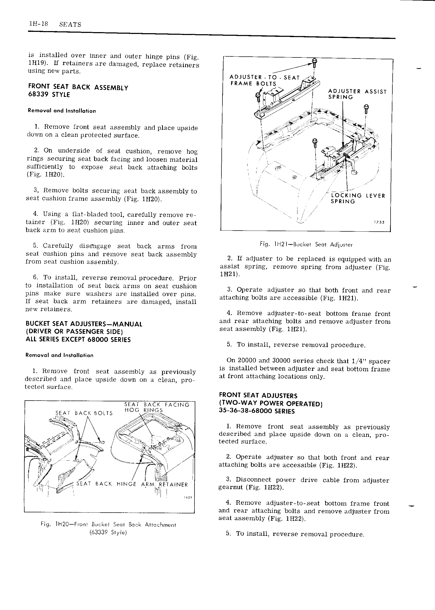
1H 18 SEATS is installed over inner and outer hinge pins Fig 1Hl9 If retainers are damaged replace retainers V using new parts ADJUSTER TO SEAT I FRAME BOLTS 7i fi FRONT SEAT BACK ASSEMBLY 5 I Aoiustsn Assnst eaaso stm SPRING nemovan md Instulluiian I s 4 2 E I g Y T1 14 Remove front seat assembly and place upside vp IY 3 down on a clean protected surface f 3I 2 w T si IvriI I 2 On underside of seat cushion remove hog I I rings securing seat back facing and loosen material 4 IMA sufficiently to expose seat back attaching bolts I FR il j Fig lH20I J I rr 3 Remvovevbolts securing seat back assembly to FOEKYNG LEVER seat cushion frame assembly Fig 1H20 SPRING 44 Using a flat bladed tool carefully remove re I 4 tainer Fig 1H20I securing inner and outer seat r IHS back arm to seat cushion pins 54 Carefully diseaigage seat back arms from FIg IH2I B kEI Sem A IIUSI r seat cushion pins and remove seat back assembly 2 H adjuster to be replaced is Equipped with Im from Sem Cushion SS I Iy assist spring remove spring from adjuster Fig 4 lH21 G To install reverse removal procedure Prior I to installation of seat back arms on seat cushion 3 Operate adjuster SO that both from and 14631 pins make sure washers are installed over pins itmchmu bolts are Accessible Fw IHZI If seat back arm retainers are damaged install D NEW mm 4 Remove adjuster to seat bottom frame front I ttih l1t da i t f Bucket s AT Amusnzks MANUAL 1 bl 4 gmifn wmove Er wm DRIVER OR PASSENGER SIDE ALL SERIES EXCEPT 68000 SERIES 5 To install reverse removal procedure R On 20000 and 30000 sei aes cheek that 1 4I 4 spacer V is installed between adjuster and seat bottom frame 1 Remove front seat assembly as previously qt from 1tt 1chin locations Only described and place upside down on a clean pro L tected surface FRONT SEAT ADJUSTERS SEAT BACK RACING TWO WAY POWER OPERATED SEM BACK DONE HOG gurguss 35 36 38 68000 SERIES riI I I 14 Remove front seat assembly as previously j af 3h I I Q described and place upside down on a clean pro ziiix qagx 0 r 3I j j II g f ii tected surface shi rp kk 1 J i 4 2 Operate adjuster so that both front and rear PI I mI V F H Ross I E attaching bolts are accessible Fig 1H22I i pw y A EQIIIM I I I mfg tI 4r I IIA gt Ij II I I 3 Disconnect power drive cable from adjuster rj U 2 SEAT BACK HINGE AVRMNRETAINER gearnut Fig IHZZ I II I T I I I II 4 Remove adjuster to seat bottom frame front r and rear attaching bolts and remove adjuster from seat assembly Fig 1H22 Fig4 II I2O FI m Bucket Sem Beck Attochmcnl 63339 SIyIeI 54 To install reverse removal procedure

 Next
Next