Jeep Parts Wiki | Ford Parts Wiki
Home | Search | Browse
|
Body Service Manual August 1964 |
|
Prev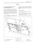
 Next
Next
110105
110105
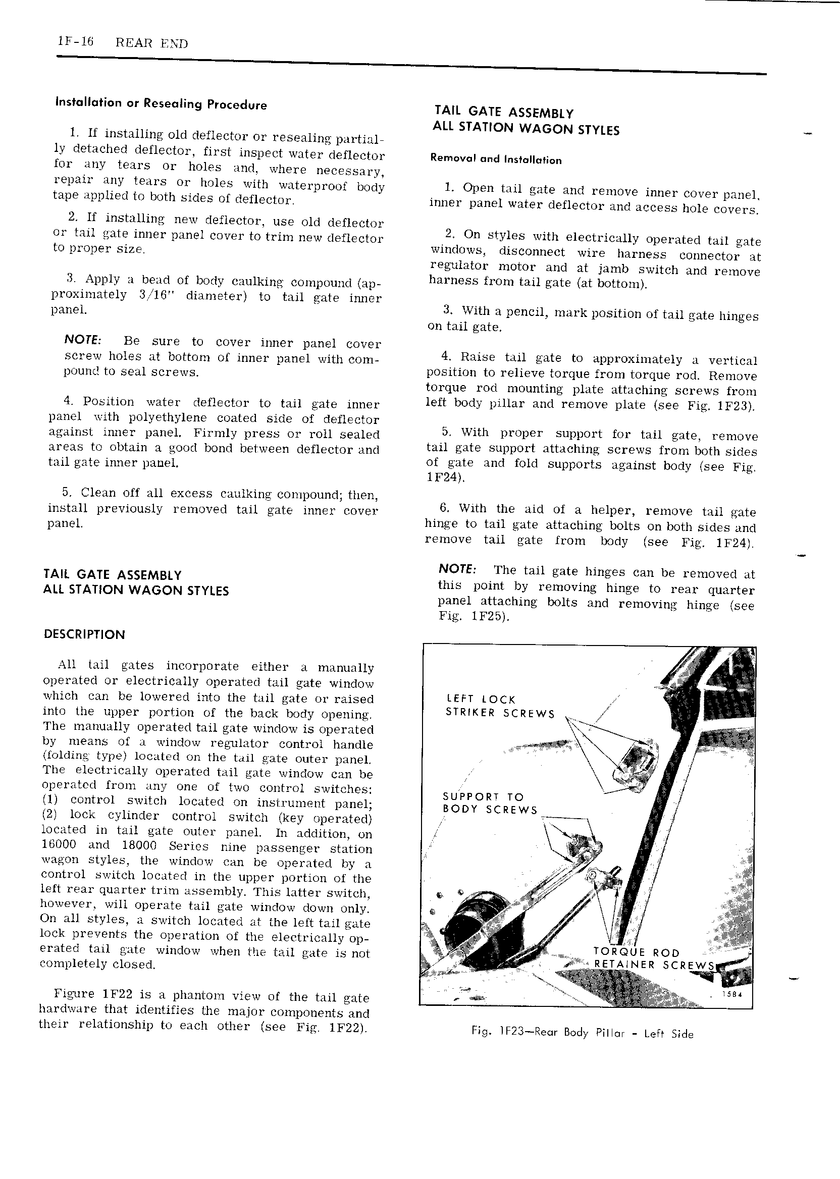
1F 16 REAR END Installation or Reseuling Procedure A GATE AggEMB y ALL STATION WAGON STYLES 1 Ii installing 01d deflector Ol 1 ese a1ing p u tiz11 ly detached deflector first inspect writer deflector Removal und Installation for any tears 01 h01 s amd where necessary repair any tears or 110105 with waterproof bmdy 1 Open mil gate and remove inner coverpniiel tape Applied t0 both sides Of deflectur inner panel water deflector and access h01e covers 2 If installing new rleflectmr use 01d deflector 9 V 01 tziil gate inner panel cuver to trim new deflector 4 1 On bmreb W1tht 1Q tmC 11y Operated tall gate tOp1 Op y SUB W1 U S CISCOHHGC wire mrness connector gt z eg 1z1nt0r motor and at jamb switch and remove 3 Apply zi bend of body cziulking compound ap harness imm 1 t at b m m vroximztsly 31G diameter t0 tail gate inner imnell 1 J With u pencil mark pusitiun of tail gate hinges 011 tail gate NOTE Be rure t0 cover inner nzmezl cover screw holes zi bottom of inner pan 1 with com 4 Raise mu gate tc approxmmtely A Vertical pound to SER1 Sc S position to relieve torque from torque rod Remove torque rod mounting plate attaching screws from 4 POSMOH wHtEI dgflecmr to mj gate inner left body pillar and remove plate see Fig 1F23 4 pzmcl with polyethylene coated side of defisctor 5 wxh t f t 1 at 7 ugixizist inner panel Firmly press 0i roll sealed 1 1 1 upP O1 al ga V areas t0 Obtain 1 good bond between deflector and tall gate PP t Attaching cli WS fl Om both big mu gate inner IEDM nigziigte and told buppoitb 1g 1m t body we Fig 5 Clean off 1111 excess czmlking compound then I 7 7 I 1 Q 1 Wt mm t t r Gd ml X 1 v i T i Zf 2 Xf L L imge 0 ai gae A acimg s n i 1 es tmc plug remove tail gate from body see Fig 1F24 NOTE The tail gate hinges can be removed at TAIL GATE ASSEMBLY this point by removing hinge to rear quarter Au STATION WAGON STYLES panel attaching bolts and removing hinge see Fig 11725 DESCRIPTION al Y A11 mil gates incorporate either u manually Q operated 0r electrically operated tail gate window A rgw which can be lowered into the trail gate or raised LEFT LOCK 1 mm me upper portion of the back body opening STMKER SCREWS x W The manually mperhtetl mil gate wiuclorv is operated mm by means ui ii window regulator control handle y J V holdin type lccuied O1 the mil gate outer panel The electrically operated tail gate window can be if operator from tiny one of two CO1it Ol switches SUPPORT TO Z 1 control switch located On instrument panel BODY gcuwsi 2 lock cylinder control switch key riperated T f located in tail gate miler panel In addition on gr 16000 and 18000 Series nine passenger station jl wagon styles the winclcnw can bc 0p 1 rxt d by A xX control s it h located in the upper portion 0f the 4 j left iwear quarter trim assembly This latter switch 6 oo K f J however will operate tail gate window down only e I I g L On 111 styles i switch located at the left tail gate A lock prevents the operation Of the electrically Op 3 H Tak i erated tml gate window when the tail gate is n0t 7 RET SlLiRR2gREWS completely closed Q 4 z N 5 mi Figure 1F22 is zi phantom view nf the tail gate t 1 u hardware that identifies the um j0r CO1I OYlGI1tS and their relationship to each other see Fig 1F22 Fig 1F23 Rear Body Pi r Lefr Side