Jeep Parts Wiki | Ford Parts Wiki
Home | Search | Browse | Marketplace | Messages | FAQ | Guest
Prev
 Next
Next
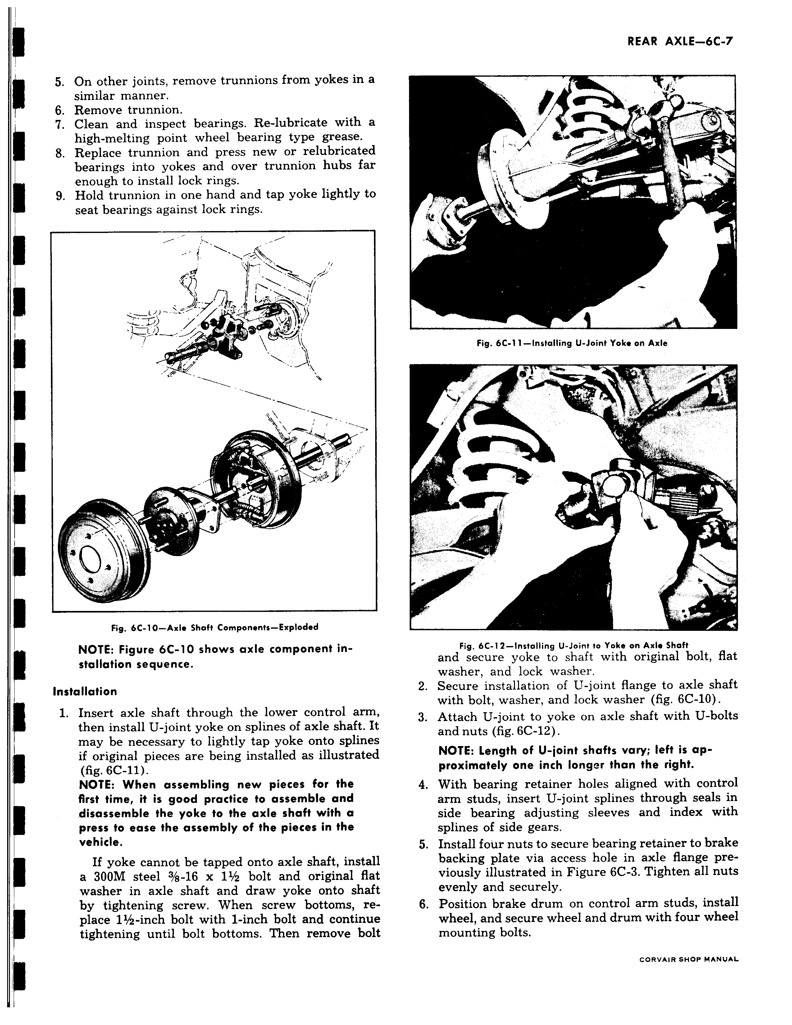
5 On other joints remove trunnions from yokes in a similar manner 6 Remove trunnion 7 Clean and inspect bearings Re lubricate with a high melting point wheel bearing type grease 8 Replace trunnion and press new or relubricated bearings into yokes and over trunnion hubs far enough to install lock rings 9 Hold trunnion in one hand and tap yoke lightly to seat bearings against lock rings j i w 1 v a Fig 6C 10 Axle Shaft Corn Ponents Exploded NOTE Figure 6C 10 shows axle component in stallation sequence Installation 1 Insert axle shaft through the lower control arm then install U joint yoke on splines of axle shaft I1 may be necessary to lightly tap yoke onto spline if original pieces are being installed as illustrated i fig 6C 11 NOTE When assembling new pieces for the first time it is good practice to assemble and disassemble the yoke to the axle shaft with a press to ease the assembly of the pieces in the vehicle If yoke cannot be tapped onto axle shaft instal a 300M steel 3 s 16 x 11 2 bolt and original flal washer in axle shaft and draw yoke onto shafv by tightening screw When screw bottoms replace 11 2 inch bolt with 1 inch bolt and continue tightening until bolt bottoms Then remove bol a I i D Fig 6C 11 Installing U Joint Yoke on Axle p r 1 Fig 6C 12 Installing U Joint to Yoke on Axle Shaft and secure yoke to shaft with original bolt flat washer and lock washer 2 Secure installation of U joint flange to axle shaft with bolt washer and lock washer fig 6C 10 3 Attach U joint to yoke on axle shaft with U bolts and nuts fig 6C 12 NOTE Length of U joint shafts vary left is approximately one inch longer than the right 4 With bearing retainer holes aligned with control arm studs insert U joint splines through seals in side bearing adjusting sleeves and index with splines of side gears 5 Install four nuts to secure bearing retainer to brake backing plate via access hole in axle flange pre viously illustrated in Figure 6C 3 Tighten all nuts evenly and securely 6 Position brake drum on control arm studs install wheel and secure wheel and drum with four wheel mounting bolts CORVAIR SHOP MANUAL