Jeep Parts Wiki | Ford Parts Wiki
Home | Search | Browse
Prev
 Next
Next
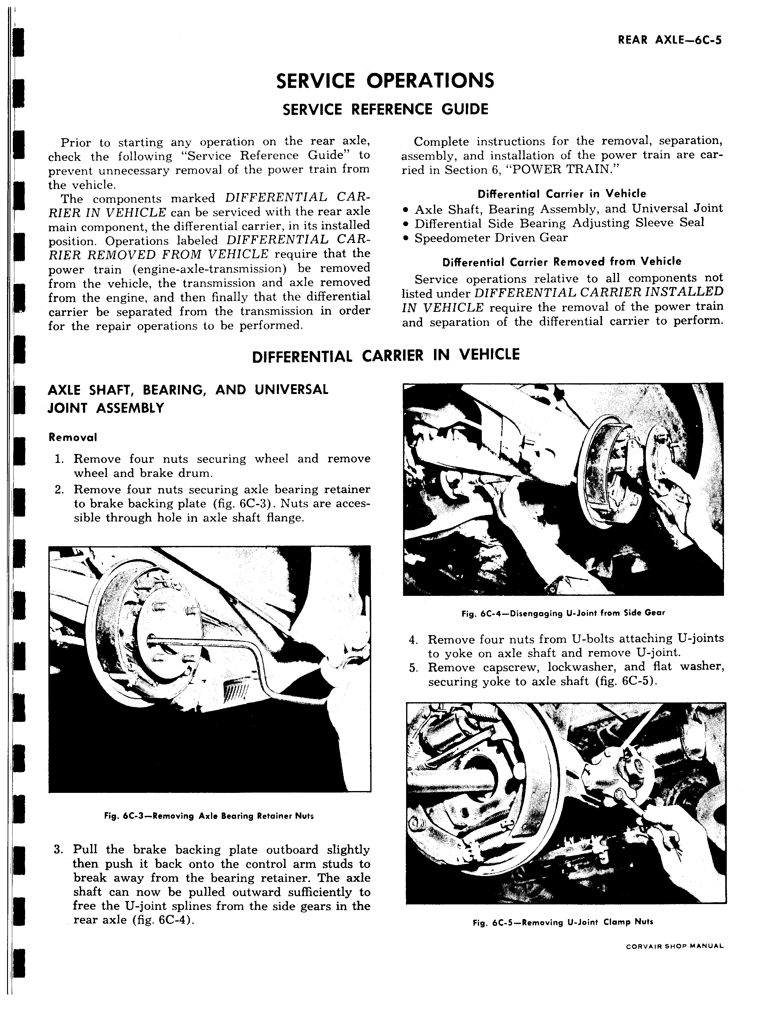
SERVICE O SERVICE REFE Prior to starting any operation on the rear axle check the following Service Reference Guide to prevent unnecessary removal of the power train from the vehicle The components marked DIFFERENTIAL CARRIER IN VEHICLE can be serviced with the rear axle main component the differential carrier in its installed position Operations labeled DIFFERENTIAL CARRIER REMOVED FROM VEHICLE require that the power train engine axle transmission be removed from the vehicle the transmission and axle removed from the engine and then finally that the differential carrier be separated from the transmission in order for the repair operations to be performed DIFFERENTIAL CA AXLE SHAFT BEARING AND UNIVERSAL JOINT ASSEMBLY Removal 1 Remove four nuts securing wheel and remove wheel and brake drum 2 Remove four nuts securing axle bearing retainer to brake backing plate fig 6C 3 Nuts are accessible through hole in axle shaft flange Itl Fig 6C 3 Removing Axle Bearing Retainer Nuts 3 Pull the brake backing plate outboard slightly then push it back onto the control arm studs to break away from the bearing retainer The axle shaft can now be pulled outward sufficiently to free the U joint splines from the side gears in the rear axle fig 6C 4 ERATIONS ZENCE GUIDE Complete instructions for the removal separation assembly and installation of the power train are carried in Section 6 POWER TRAIN Differential Carrier in Vehicle Axle Shaft Bearing Assembly and Universal Joint Differential Side Bearing Adjusting Sleeve Seal Speedometer Driven Gear Differential Carrier Removed from Vehicle Service operations relative to all components not listed under DIFFERENTIAL CARRIER INSTALLED IN VEHICLE require the removal of the power train and separation of the differential carrier to perform tRIER IN VEHICLE 0 MM t Fig 6C 4 Disengaging U Joint from Side Gear 4 Remove four nuts from U bolts attaching U joints to yoke on axle shaft and remove U joint 5 Remove capscrew lockwasher and flat washer securing yoke to axle shaft fig 6C 5 a 01 Fig 6C 5 Removing U Joint Clamp Nuts CORVAIR SHOP MANUAL