Jeep Parts Wiki | Ford Parts Wiki
Home | Search | Browse
|
Body Service Manual August 1964 |
|
Prev
 Next
Next
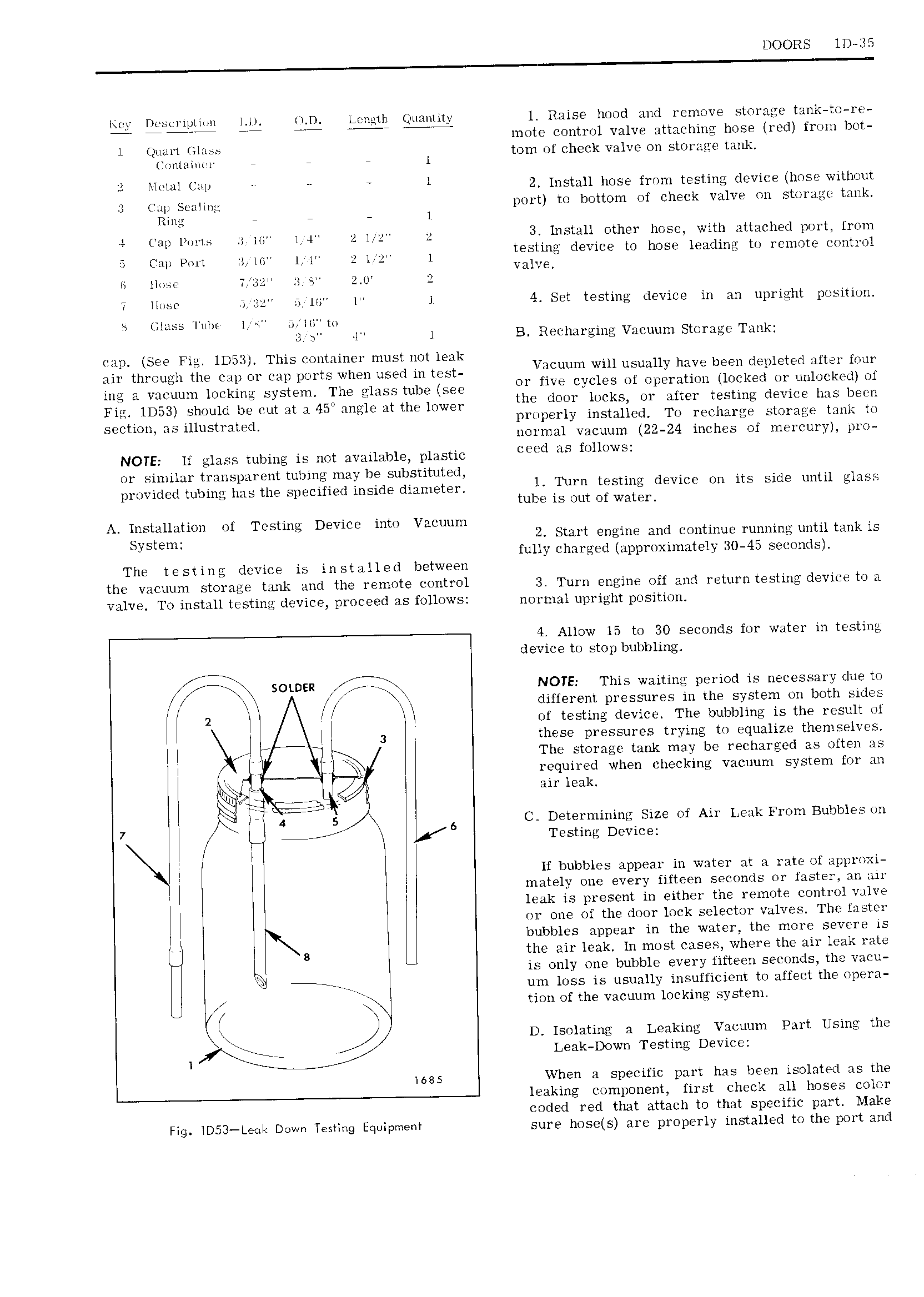
DOORS ID 35 key Dcsti ip1i ii 1 1 D Lenefli t nan1i1y l Raise hood and remove storage tank to re 7 774 Tir A7 7 mote control valve attaching hose red from bot Jil 1i i t 1 ij i 1 tom of check valve on storage tan 2 i i i 1 i 2 Install hose from testing device hose without 3 Cup Senlnna port to bottom of check valve on storage tank Ring 1 V Cup mms H W 1 4 2 I 2 3 Install other hose with attached port Iroin CHI PNN It Mn I L 2 l l testing device to hose leading to remote control 1 llosc T 52 a 2 u VA GA T llosc 3 6 li 1 1 4 Set testing device in an upright position s llinss Tube 1 J 1 1 tt za s 11 1 B Recharging Vacuum Storage Tank cap See Fic lD53 This container must not leak an tiimugii the mp 1 mp ports when used in test V Wm S uY h Y d l X ing a vacuum locking system The giass tube see me Cycles f iwked 1 k Fm IDSB Should be out at H 45 mm1 at uw IOWET the door locks or atter testing device has been Section as illustrated properly installed To recharge storage tank to normal vacuum 22 24 inches of mercury pro NOTE If glass tubing is not available plastic Cegd 35 KNOWS or similar transparent tubing may be substituted provided tubing has the specified inside diameter Turn testing 1Evi rm its Side until 3 tube is out of water A Installation of Testing Device into Vacuum Svstem V 2 Start engine and continue running until tank is fully charged approximately 30 45 seconds The testing device is installed between the vacuum storage tank and the remote control 3 Turn engine off and return testing device to a valve To install testing device proceed as follows normal upright position 4 Allow 15 to 30 seconds for water in testing device to stop bubbling SOLDER NOTE This waiting period is necessary due to xi 1 yr J y different pressures in the system on both sides 2 i i i of testing device The bubbling is the result of i 3 these pressures trying to equalize themselves i i 1 ri i The storage tank may be recharged as often as i i i li required when checking vacuum system for an i air leak 7 ji W 4 5 6 C Determining Size of Air Leak From Bubbles on W Testing Device Vi N i If bubbles appear in water at a rate of approxi 1 I mately one every fifteen seconds or faster an air leak is present in either the remote control valve i or one of the door lock selector valves The taster 1 p bubbles appear in the water the more severe is B the air leak In most cases where the air leak rate is only one bubble every fifteen seconds the vacu i tr erV um loss is usually insufficient to affect the opera i j tion of the vacuum locking system In J D Isolating a Leaking Vacuum Part Using the Leak Down Testing Device 1685 Vhen a specific part has been isolated as the leaking component first check all hoses color coded red that attach to that specific part Make Fig iD53 Lecii Down Testing Equipment sure hosets are properly installed to the port and