Jeep Parts Wiki | Ford Parts Wiki
Home | Search | Browse | Marketplace | Messages | FAQ | Guest
|
Body Service Manual August 1964 |
|
Prev

 Next
Next
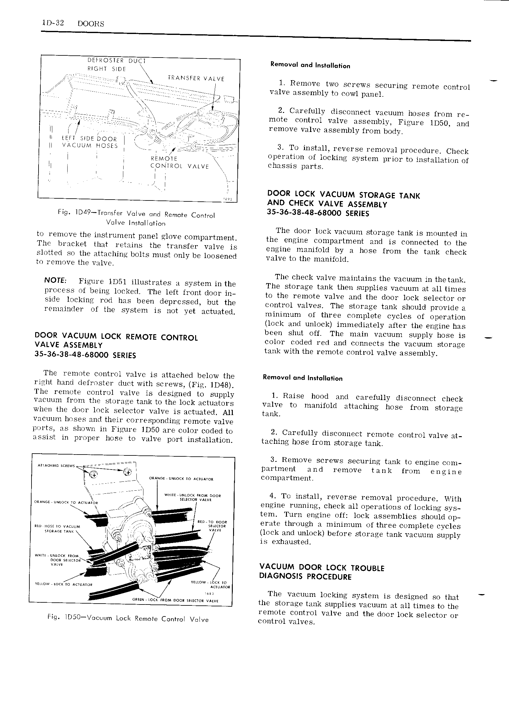
1D 32 DOORS DEFHOSTER Doijl Removal and Instulluticn Mont Sine L lL j L j LLLLTTi TSTET VAHVE 1 Remove two screws securing remote control r r V rrrr rrrr r valve assembly to cowl panel so e V Y rrrrrr I r r 21 Vrrr L L l L r rr 2 Carefully disconnect vacuum hoses from re L L L L L L jL L rrrrr L L mote control valve assembly Figure lD50 and LL L L j L g remove valve assembly from body il LEFT Arne noon L T g LL M L U L HOSE L L L 3 To install reverse removal procedure Cheek L L L PLMLDLL operation of locking system prior to installation of LL L L CONTROL VALVE chassis parts l l Q l i DOOR LOCK VACUUM STORAGE TANK AND CHECK VALVE ASSEMBLY mg i i T Gm vat e C a 3 E V I I r Il r G VE M G G Ion The door lock vacuum storage tank is mounted in to remove the instrument panel glove compartment the engine compartment and is connected to the The bracket that retains the transfer valve is engine manifold by a hose from the tank check slotted so the attaching bolts must only be loosened valve tg the mHnifO d to remove the valve The check valve maintains the vacuum in the tank NOTE Figure lD5l illustrates a system in the The storage tank then supplies vacuum at all times process of being locked The left front door in to the remote valve and the door lock selector or Side leekirta Ml has been deinrvssed but the omtmi valves The storage tank should provide a remainder of the system is not yet actuated minimum of three complete cycles of operation lock and unlock immediately after the engine has been shut off The main vacuum supply hose is DOOR VACUUM LOCK REMOTE CONTROL color coded red and connects the vacuum storage VALVE ASSEMBLY tank with the remote control valve assembly 35 36 38 48 68000 SERIES The remote control valve is attached below the Removul und lnst lI ion right hand defroster duct with screws Fig lD4B The remote control valve is designed to sup ly l Raise hood and carefully disconnect check l vacuum from the storage tank to the lock actuators valve to manifold attaching hose from storage when the door lock selector valve is actuated All tank vacuum hoses and their corresponding remote valve ports as shown in Figure 1D50 are color coded to 2 Carefully disconnect remote control valve at assist in proper hose to valve port installation taching hose from storage tank L 3 Remove screws securing tank to engine com u iTl partment and remove tank from engine f L l iw t ei t c 7 iTl ww i N m mM aO 4 To install reverse removal Jrocedure With i 4 Samui vim I eE v sQ muifm L XK A engine running check all operations of locking sys E T tem Turn engine off lock assemblies should op if V 7 L E g erate through a minimum of three complete cycles M ii Llf iLY lL LL L lock and unlock before storage tank vacuum supply L gg nin is exhausted ax ea ZT 5 f t3Q lm rr VACUUM DOOR LOCK TROUBLE jt e M l f DIAGNOSIS Pnocenune we www iw ye L The vacuum locking system is designed so that G M the storage tank supplies vacuum at all times to the remote control valve and the door lock selector or Fig lD50 ocuum Lock Remote Control lve control valves

 Next
Next