Jeep Parts Wiki | Ford Parts Wiki
Home | Search | Browse
|
Body Service Manual August 1964 |
|
Prev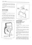
 Next
Next
4480378
4480378
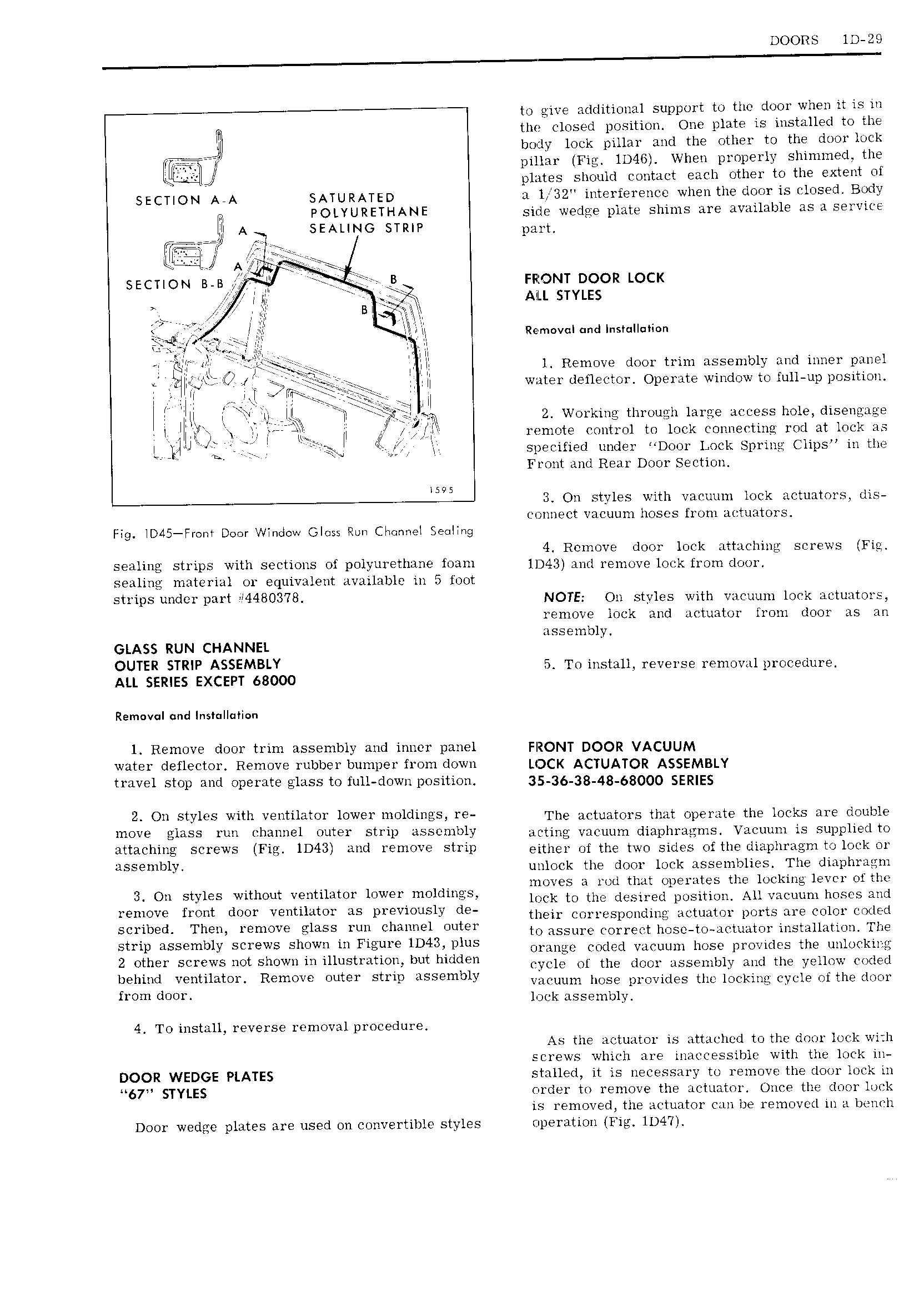
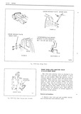
DOORS lD 29 to give additional support to the door when it is in W the closed position One plate is installed to the lt body lock pillar and the other to the door lock pillar Fig 1D4G When properly shinimed the plates should contact each other to the extent of SECTION AeA SATU RATED a l 32 interference when the door is closed Body at POLYURETHANE side wedge plate shims are available as a service 7777JtN An SEALING STRIP pgytl Ulmer A D eeee SECTION B B FRONT DOOR LOCK t It V y A I L STYLES nj Remvcnqnd I s nn ia n T ti Elf r l Remove door trim assembly and inner panel J yfttt t E f wr cig II water dellector Operate window to full up position 1 I w e rrrr 1 II t I ytll I E j li tj y 2 Working throue h large access hole disengage l tl WL TI L tt 1 10t9 ontr0l to lock Connecting rod at look as L t ii J Specified under Door Lock Spring Clips in the Front and Rear Door Section iws 3 On styles with vacuum lock actuators dis connect vacuum hoses from atztuators Fig ID45 Fr m Door Window Gloss Run CI neI Seelmg 4 Remove door lock attaching screws Fla sealing strips with sections of polyurethane loam lD43 and remove loick from door sealing material or equivalent available in 5 foot strips under part 4480378 NOTE On styles with vacuum lock actuators remove lock and actuator lrom door as an ass e mbly GLASS RUN CHANNEL OUTER TR P ASSEMBLY 5 To install reverse removal procedure ALL SERIES EXCEPT 68000 Removal und Ins II i n l Remove door trim assembly and inner panel FRONT DOOR VACUUM water deflector Remove rubber bumper from down LOCK ACTUATOR ASSEMBLY travel stop and operate glass to full down position 35 36 38 48 63 0 5ER E 2 On styles with ventilator lower moldings re The actuators that operate the locks are double move glass run channel outer strip assembly Mtiyig vaijuum diapliragms Vacuum is supplied to attaching screws Fig 1D43 and remove strip either of the two sides of the diaphragm to lock or assembly unlock the door lock assemblies The diaphragm moves a rod that operates the locking levcr of the 3 On Styles wlthout veutuatm IOWQI 1 e lock to the desired position All vacuum hoses and YEHTOVG from dm VEMHMOY as previously de their corresponding actuator ports are color coded S 1ilb9d Them mmmve ees nu Channel Outer to assure correct hose to actuator installation The Etup SS lv Screws Sh wtl m Flgljuwe 1D43 DtuS orange coded vacuum hose provides the unlocking 2 Other S WS mt S W m i 1 S v ph e one of the tm issmbiy and the eim uai behmd f Veutlmtolh Remmle Jute stmt u5 9mb1Y vacuum hose provides the locking cycle oi the door from d J Y lock assembly 4 To install reverse removal procedure As the actuator is att u hed to the door lock with screws which are inaccessible with the lock in DOOR WEDGE PLATES stalled it is necessary to remove the door lock in 67 STYLES order to remove the actuator Once the door lock is removed the actuator can be removed in a bench Door wedge plates are used on convertible styles operation Fig lD4 7 I