Jeep Parts Wiki | Ford Parts Wiki
Home | Search | Browse
|
Body Service Manual August 1964 |
|
Prev
 Next
Next
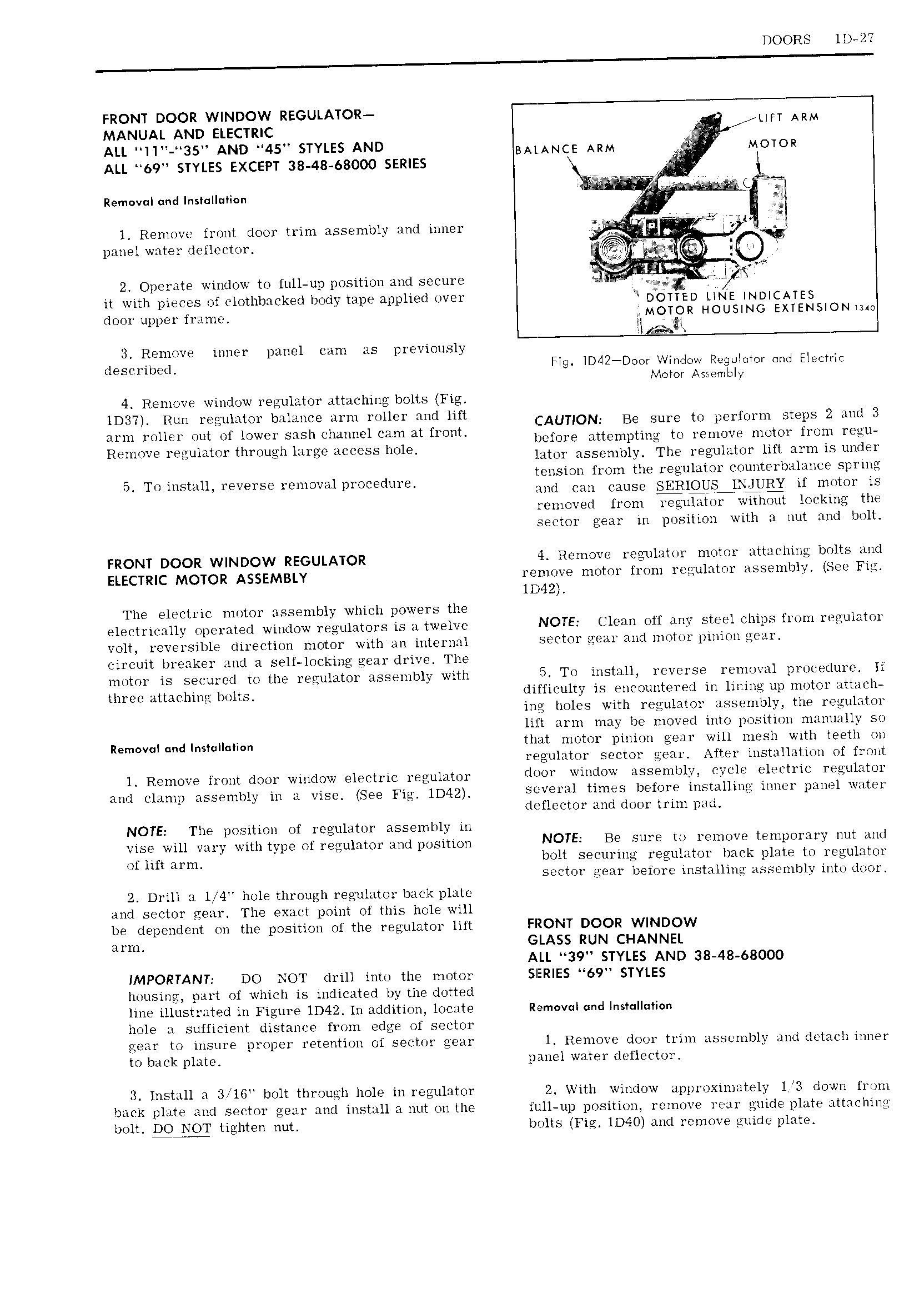
DOORS ll 27 FRONT DOOR WINDOW REGULATOR MANUAL AND euzcmc LIFT ARM ALL I 35 AND 45 STYLES AND BALANCE ARM H MOTOR ALL 69 STYLES EXCEPT 38 48 68000 SERIES nemowi and In II ea l Remove front door trim assembly and inner A r 1 Ifl panel water deflector I 2 Operate window to full up position and secure Q I 1 l ml iil it with pieces of clothbacked body tape applied over DOIIIED Inj INDICATES door upper frame MOTQR HOUSING EXTENSION Iam I m 3 Remove inner panel cam as previously described Fig ID4Z D r Window Regotevor ond Electric Motor Assembly 4 Remove window regulator attaching bolts Fig lD37 Run regulator balance arm roller and lift CAUTION Be Sure to p 1 I m m Steps 2 md 3 gm ollcr out of lower aSl ll 1t1i l dt Wil I CI m E attempting to remove motor from reeli Emme gI 1I m u th1mIghl ug ILLGST hI 1 I ator assembly The regulator lift arm is under 5 TO mqwu 1 V 1 E x mUV 11 p1 OCE dm tension from the regulator counterbalance spring and can cause SERlQUS lNiUljQ if motor is removed from Qulator without locking the sector gear in position with a nut and bolt FRONT DOOR WINDOW REGULATOR 4 Remove regulator motor attaching bolts and ELECTRIC MOTOR ASSEMBLY remove motor from regulator assembly See Fig lD l2 The electric motor assembly which powers the electrically operated window regulators is a twelve NOTE Clean off any steel chips from regulator volt reversible direction motor with an internal sector gear and motor pinion gear circuit breaker and a self locking gear drive The motor is secured to the regulator assembly with To install reverse removal procedure lf three attaching bolts difficulty is encountered in liring up motor attach ing holes with regulator assembly the regulator lift arm may be moved into position manually so Remcvulcndlnstullulion that motor pinion gear will mr sh with teeth on regulator sector gear After installation of front l Remove front door window electric regulator fI J01 Wi d W BSSBIHIJIYI Pf Cl 1 i T1 liI r gul it Jr and clamp assembly in a vise See Fig 1D42 S V l 3l times before installing inner pane water deflector and door trim pad NOTE The position of regulator assembly in vise will vary with type of regulator and position NOTE B6 Sm li i m JV It ml 1 Y i Y NUT ll I of INI m m bolt securing regulator back plate to regulator sector gear before installing assembly into door 2 Drill a lt 1 hole through regulator back plate and sector gear The exact point of this hole will be dependent on the position of the regulator lift FRONT DOOR WINDOW arm GLASS RUN CHANNEL ALL 39 STYLES AND 38 48 68000 IMPORTANT DO NOT drill into the motor SIERIES 69 STYLES housing part of which is indicated by the dotted line illustrated in Figure lD42 In addition locate Removal and Insr II ion hole a sufficient distance from edge of sector gear to insure proper retention of sector gear 1 Remove door trim assembly and detach inner to back plate panel water deflector 3 lnstall a 3 IG bolt through hole in regulator 2 With window approximately 1 3 down from back plate and sector gear and install a nut on the full up position rcmovc rear guide plate attaching bolt tighten nut bolts Fig ll 40 and remove guide plate