Jeep Parts Wiki | Ford Parts Wiki
Home | Search | Browse
|
Body Service Manual August 1964 |
|
Prev
 Next
Next
4480378
4480378
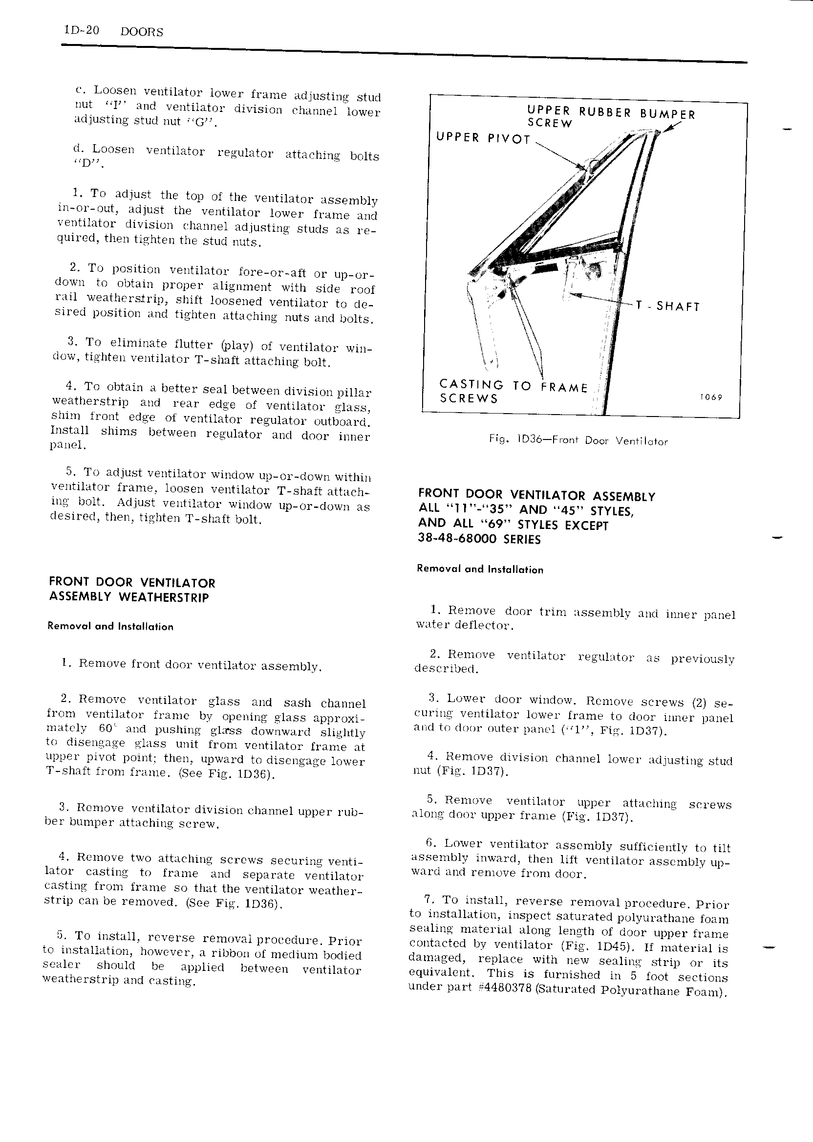
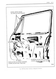
lD 2O DOORS e Loosen ventilator lower frame adjusting stud nut l and ventilator division ehannel lower RUBBER BUMPER adjusting stud nut G VZ UPPER PIVOT d Loosen ventilator regulator attaehing bolts Fvi l To adjust the top of the ventilator assembly j in or out adjust the ventilator lower frame and VI I ventilator division channel adjusting studs as re quired then tighten the stud nuts V i 4 lr II lx g 2 To position ventilator fore or att or up or af fg down to obtain proper alignment with side roof H l i rail weatherstrip shift loosened ventilator to de Y at TT SHAFT sired position and tighten attaching nuts and bolts l E 4 3 To eliminate flutter play of ventilator win I Xt wl dow tighten ventilator T shaft attaching bolt hq CASTING TO FRAME 0 4 To obtain a better seal between division pillar SC REWS 69 weatherstrip and rear edge of ventilator glass shim front edge of ventilator regulator outboard Install shims between regulator and door inner Fig lD3 Fmm Door entllolor panel 5 To adjust ventilator window up or down within ventilator frame loosen ventilator T shaft attach FRONT DOOR VENTILATOR ASSEMBLY ing bolt Adjust ventilator window up or down as ALL ll 35 AND 45 STYLES desired then tighten T shaft bolt AND ALL 69 STYLES EXCEPT 38 48 68000 SERIES Removal und lnst ll i n FRONT DOOR VENTILATOR ASSEMBLY WEATHERSTRIP 1 Remove door trim assembly and inner panel water defleetor Removal and lnstullumm 2 Remove ventilator regulator as previouslj l Remove front door ventilator assembly described 3 Lower door window Remove serews 2 se 2 Remove ventilator glass and sash Channel VV V V V 7 o V I j lr vuring ventilator lowei tame to door innei panel hom nentivlator Ilsllllti yy opening g ass J 1t Xl HH 1tUd m1 nutE l PmVHr 1 1 IDM matelj GO and pushing glxss downward slightly Ul dlseliguge glass mm from veuhiamr Hume at 4 Remove division ehannel lower adjusting stud upper prvot point then L1p lll d to dlS l1 l CG l W l nut Fin IDIW V T shaft from frame See Fig lD3G K 5 Remove ventilator upper attaelnng serews 3 Remove ventilator division ehannel upper rub along door upper frame Fig lD3 l ber bumper attaching screw G Lower ventilator assembly suffieiently to tilt V V V VV assemblv inward then lift ventilator assembly up 4 Remove two attaching screws securing venti j o V ward and remove from door lator casting to frame and separate ventilator eastmg from frame so rthat the veigtilator weather T To install l G 1 SQ 1 61 1 1p1 U V du Prim sti ip can be removed see Fig 1D 6 to installation inspect saturated polyurathane foam sealing material along length of door u per frame V l 5 To install reverse removal proeedure Prior eontaeted by ventilator Fig lD45 lf material is to installation however a ribbon of medium bodied damaged replaee with new sealing strip or its sealer should be applied between ventilator equivalent This is furnished in 5 foot sections weatherstrip and Fasting under part 4480378 Saturated Polyurathane Foam