Jeep Parts Wiki | Ford Parts Wiki
Home | Search | Browse | Marketplace | Messages | FAQ | Guest
|
New Product Service Information Manual 201 January 1972 |
|
Prev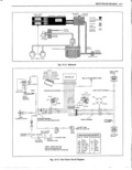
 Next
Next
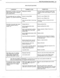
V i 15 8 TRUETRACK BRAKE DIAGNOSIS moves down against spring pressure allowing piston to move False Release down shutting off presnlre from the master cylinder As the The True Track Braking System s basic function is to piston moves down it opens up a chamber in the moculator maintain stability during maximum effective stops by i travel switch to bleed off some of the pressure from the keeping the rear wheels from skidding This action can take rear brake lures thus releasing the brakes place at varying degrees of brake pedal effort as determined During maximurln braking stops the modulator by brake effectiveness slipper iness of road nrrface etc i continues to cycle and pxunp the rear brakes until the car and normal cycling will be experienced when the controller I ipe rsh reduced to 5 mph or until the brakes are released senses the rgar wheel starting to look ug This is Ligomal y e rver operation ycling o the system ran om or o erwise Q when not braking the car or when light normal brake stops are being made would be considered false releases i DIAGNOSIS Diagnosis or the True Track Brake s stem should be WARNING l lGl lf inane in two parts Hydraulic and elcctroiliic malfunctions 4 The wnrnlns lidrt lyented nn the insnnnrent pnnel i eari be separated by aiseoriiiectiiig the nioaiiiator solenoid nldlentes parkrns brake 0N Jes nf prennre in front cr i 2 wire connector ltiirakine problem is corrected use me rear brake system er malfunction of the True Track diagnosis charts to determine correction to the problem If Brnlnng System The warning light operates in eenivnetien the problem still exists ir is in the hydraulic system di with the modulator travel switch and controller to provide power brake unit and is diagnosed the game as any a visual indication of a malfunciton lasting more than four hydraulic system except rear brake hydraulic pressure seconds passesl through the modulator When the modulator solenoid is disconnected this passage should be open to MOBILE RADIO TRANSMITTERS allow pressure to rear brakes Before starting diagnosis Mtlbl le rndie ll S ll lll llllPll l l l ie Sllblect te ma ce ctiitain gxuum is available to the power brake unit gederdago rnlpunicadrgl Cfmigissioixegulatiolnls and mir an to emo ator e inst e y a qu iie ra io te nician e spec ic W hen troubleshooting certain basie knowiedge gf the installation inscmctions fonradio transmitters will vary system can be very helpful The following general depending upon the radio equipment used Mobile mformation is presented for this reason r e gl i S i l n l 1ll l ed al 1 5 1 aigggvlsgrge a i s c r OPERATIONAL CHECK openers will not adversely affect vehicle eration In the event any other type of mobile radio traongmitter is to be NOTE Do not exeyg heavy pressure on the brake Pedal installed further instructions are required so that car diiging the fepinwmg pest as damage my Own in pw operationwill not be adversely affected br e system Raise and support rear end of car so that rear wheels are TSJGATEC lvmmc Fig 15 3 above the Hoon mac mnmmion m park gd block hem Tlrgnglectric gil ale circuit has been cha ed so that the rl lSipsr E rZeihEpi pgZ j ill pVZl i T l1 l i Yrldwli i nie een be eee eel or eleeed with the eneqie en er eff if apply apap na prime rear Wheel ror pypiipp rr rea thlgeeleggerleveyenne tr gl1gen k f e gg televen wheel stops immediately when the brake is applied the IE dy gmun m u gh eneetr me FWM system is inoperative Repeat tor pap rear Wren ee eeeer eeleneel Gwent ere el the relay te net enough to energize the starter solenoid DEFINITION OF TERMS IN DIAGNOSIS CHARTS Iirunediate Brake Light The brake light comes on immediately when the igiition switch is turned to the on position Delayed Brake Light A delayed brake light comes on two or more seconds after the ignition switch is turned to the ON position or the engine is started normally a 2 5 second delay When a delayed brake light is encountered it is V norma lly the result of self dieck circuitry detecting a problem in the system Exercise Cycle Each time the ignition switch is turned 0N the controller sends a short signal to the solenoid modulator assembly This signal energizes the solenoid valve which in i turn allows the modulator to partially cycle if there is vacuum in the system This exercise cycle can be detected lr audibly or by feeling the modulator while someone turns pi the ignition switch ON