Jeep Parts Wiki | Ford Parts Wiki
Home | Search | Browse | Marketplace | Messages | FAQ | Guest
|
New Product Service Information Manual 201 January 1972 |
|
Prev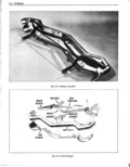

 Next
Next
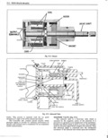
TRUE TRACK BRAKIZNG the dust cap The changing air gap between the teeth of the stator and rotor induces an AC voltage into the coil t Description The frequency of this voltage is proportional to the True Track Braking System JL9 Option is designed te number of teeth and speed of the rotor that is driven by the improve directional control of the car by automatically lea Wh l Fl l5 2 pumping the rear brakes This in turn will achieve on the average a shorter stopping distance by providing the CONTROLLER average brake pressure neeessary fur maximum stepping The Controller is mounted behind the glove box and is terse when are rear brake pressure is insufficient to cause thc computing unit of thc True Track Brrkhis SY t m This lookup the brake system operates in the mrmisl mamiep unit contains an electronic circuit The circuitry is covered During maximum braking steps the rear brake piesnire with a protective coating and encased in a plastic housing J would be sufficient to pause ldekup This impending idekup Electrical connections are made to the car harness by two would be sensed and the rear brakes weuiri be plus in cohncc ors Fis 15 4 automatically released and applied at s rate ef The Controller receives and continuously monitors the approximately 2 to 4 cycles per second The cycling lllP t spccd 615 f 0 l the two wheel SP d S llS S Us continues throughout the maximum bmkmg step until the basic functions are to determine from the input speed signal ear is slowed to approximately five miles per hour or umn when iw Whoollo l u1 is about ic occur to zchciaro an the brakes are released by tl re driven electrical output which automatically releases the rear r Each time the ignition key is turned to the on brakes to determine when therear whee1lockup situation position the Tme Track Braking system is operated for one Y0 Xl and W l 0V the P 31 which 8 l cycle of tem release and apply This exercise eyere may be applies thc roar brakes Tho Controller accomplishes its heard and is normal basic functions by modifying t he wheel speed signal to form a second signal simulating car speed Both wheel speed WHEEL SPEED SENSORS Fig 15 1 and car speed signals are then compared When their 1 I l1e wheel speed sensor is a mechanically driven difference increases to a predetemiined value the electromagnetic device that produces an AC voltage with Controller generates thc output brake release signal which frequency proportional to the input shaft speed Basic automatically releases the rear brakes With the rear brakes components of the sensor are a coil permanent magnet released wheel speed increases and when the difference stator and rotor between the wheel speed and car speed signals decrease to a The sensors are threaded into the rear wheel spindles predetermined value the Controller removes the output and driven through the spindle by a long shaft attached to brake release signal which automatically applies the rear BAND r M J li r l I r TUBE ASSEMBLY rp 4 it mam j HARNESS BAND To T SENSOR SPEED N s l i in if A I J i T W ji SPINDLE l e Ei V CLAMP 5 soot T V casm Fig 15 1 Wheel Speed Sensors ri