Jeep Parts Wiki | Ford Parts Wiki
Home | Search | Browse
|
New Product Service Information Manual 201 January 1972 |
|
Prev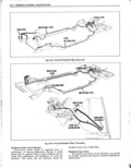
 Next
Next
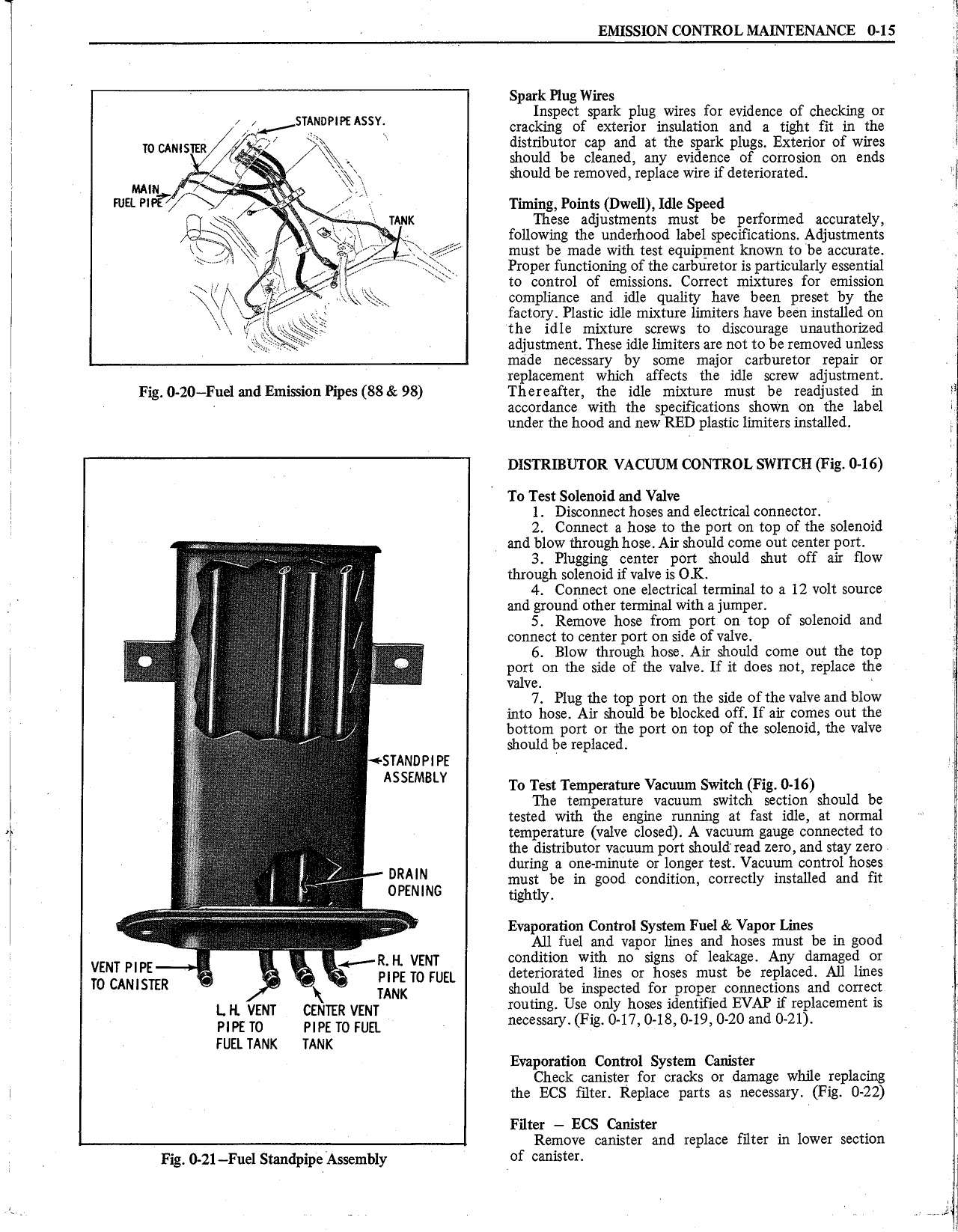
n Y EMISSION CONTROL MAINTENANCE 0 15 g A V Spark Plug Wires f f Inspect spark plug wires or evidence 0 checking or T zsWl P P sY cracking of exterior insulation and a tight tit in the R i r l iiaild 2 y Z i r aP iis E Z EEZ Z I l should be removedjreplace wire if deteriorated wma t Yay NFL PM A I yr 1 uu1ug rau a oweu 1a1e speed TANK These adjustments must be performed accurately 1 l r l following the underhood label specifications Adjustments l aq fi must be made with test equipment known to be accurate fu i Proper functioning ofthe carburetor is particularly essential t A T to control of emissions Correct mixtures for emission y Q compliance and idle quality have been preset by the x y Ng factory Plastic idle mixture limiters have been installed on X the idle mixture screws to discourage unauthorized tg adjustment These idle limiters are not to be removed unless made necessary by some major carburetor repair or replacement which affects the idle screw adjustment Fig 0 20 Fuel and Emission Pipes 8S 98 Thereafter the idle mixture must be readjusted in i accordance witl1 the specifications shown on the label under the hood and new RED plastic limiters installed l DISTRIBUTOR VACUUM CONTROL SWITCH Fig 0 16 l To Test Solenoid and Valve Q l Disconnect hoses and electrical connector 2 Connect a hose to the port on top of the solenoid and blow through hose Air should come out center port ii r e r t 3 Plugging center port should shut off air flow V through solenoid if valve is OK 4 Connect one electrical terminal to a 12 volt source and ground other terminal with a jumper I atl 5 Remove hose from port on top of solenoid and Jl connect to center port on side of valve St 7 i 6 Blow through hose Air should come out the top l T port on the side of the valve If it does not replace the 1 7 valve T g 7 Plug the top port on the side of the valve and blow l into hose Air should be blocked off lf air comes out the I lx bottom port or the port on top of the solenoid the valve is should be replaced smuurwr ASSEMBLY ra rea Temperature Vacuum swatch Fig ons The temperature vacuum switch section should be tested with the engine mnning at fast idle at normal temperature valve closed A vacuum gauge connected to the distributor vacuum port should read zero and stay zero I DRAIN during a oneminute or longer test Vacuum control lgostes rr must be in good condition correctly installed an 1t 1 OPENING tighuy mr t g r Evaporation Control System Fuel Vapor Lines ua All fuel and vapor lines and hoses must be in good 4 R H v5N1 condition with no signs of leakage Any damaged or VENT PIPE T 2 pjpg 10 FUEL deteriorated lines or hoses must be replaced All lines T0 CANISTFR shou ld be inspected for proper connections and correct L H VENT CPNTER VENTYANK routing Use only hoses identified EVAP if replacement is PIPE To PIPE TO FUEL necessary Fig 0 17 0 18 0 19 0 20 and 0 21 FUEL TANK TANK T Evaporation Control System Canister J Check canister for cracks or damage while replacing 1 T the ECS filter Replace parts as necessary Fig 0 22 Filter ECS Canister Remove canister and replace filter in lower section Fig 0 21 Fuel Standpipe Assembly f j T T 4