Jeep Parts Wiki | Ford Parts Wiki
Home | Search | Browse
Prev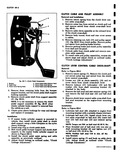
 Next
Next
CORYAIR 95 AND OR 1 Page General Description 6B 7 Maintenance and Adjustments 6B 7 Clutch Linkage Adjustment 6B 7 Service Operations 6B S Clutch Pedal Assembly 6B 8 I Removal and Installation6B 8 Clutch Cable Assembly 6B 9 I GENERAL I A diaphragm spring clutch is used with the stand ard transmission The clutch consists of two basic assemblies The clutch is attached at the front of the engine to the flywheel and is completely enclosed by the flywheel housing fig 6B 1 The driven disc is solid mounted The input shaft from the clutch to the transmission is flexible torsionally thus eliminating the need for springs in the clutch disc The clutch is operated with a conventional clutch fork except that it is shorter and operates by pulling instead of pushing The clutch fork engages the throw out bearing which is piloted on the axle housing fig 6B4 A clutch lever control rod 22 fig 6B 12 is MAINTENANCE J CLUTCH LINKAGE ADJUSTMENT Refer to Figures tiB 12 and 6B 13 1 Before starting actual adjustment check front end of the clutch controls for the following a Proper location of pedal bumper b Front return spring hooked up and operating properly c Front cable clamp properly installed and tightened NOTE The pedal should have of least 4 travel before the clutch release bearing on sages gages the diaphragm 2 Disconnect rear clutch return spring 4 NOTE Front clutch return spring is to remain operative in order that pedal bumper N In can fact with toe board ft 6 131 3 Remove retainer clip 20 clevis pin and flat washer from clutch control idler lever and remove rear cable clevis 18 EEIi1aR1ER 1Z00 SERIES IDEX Page Removal and Installation 613 9 Clutch Pull Rod 6B 9 Removal and Installation 613 9 Troubles and Remedies 6B 10 SpeciBcations 6B 10 special Tools 6B 11 DESCRIPTION attached to the end of the clutch fork and to the clutch control lever cable clevis 19 fig t3B 12 One end of the clutch control idler lever 9 fig tiB 12 is attached to a bracket mounted to the engine front mounting bracket and the other end to a clevis attached to the cable assembly Five cable retaining clamps are used to route the cable assembly from the front to the rear The Service Information and Procedures outlined for Corvair 500 700 and 900 models also apply in general to Corvair 95 and Greenbrier 1200 Series except for Maintenance and Adjustments and Service Operations outlined below MID ADJUSTMENTS 4 Allow clutch fork pull rod idler lever 22 to hang free Use as a guide to maintain correct line of action of cable clevis S Pull rearward on cable clevis to insure that all slack is removed from that point forward 8 Manually pull the clutch fork pull rod 22 fig 6B 12 until slack is taken up at clutch fork The clutch release bearing touching clutch diaphragm fingers T With the cable clevis held in position step 5 and with pull rod 22 in position described in Step 6 adjust pull rod clevis 19 to align holes in both clevis 8 With this position of the pull rod clevis 22 established unscrew clevis 22 3 turns lengthening rod by 2 9 Tighten pull rod clevis jam nut 21 Line up holes in cable clevis pull rod clevis and clutch fork pull rod idler lever 6 Insert clevis pin and retainer clip 10 Install clutch return spring