Jeep Parts Wiki | Ford Parts Wiki
Home | Search | Browse
Prev
 Next
Next
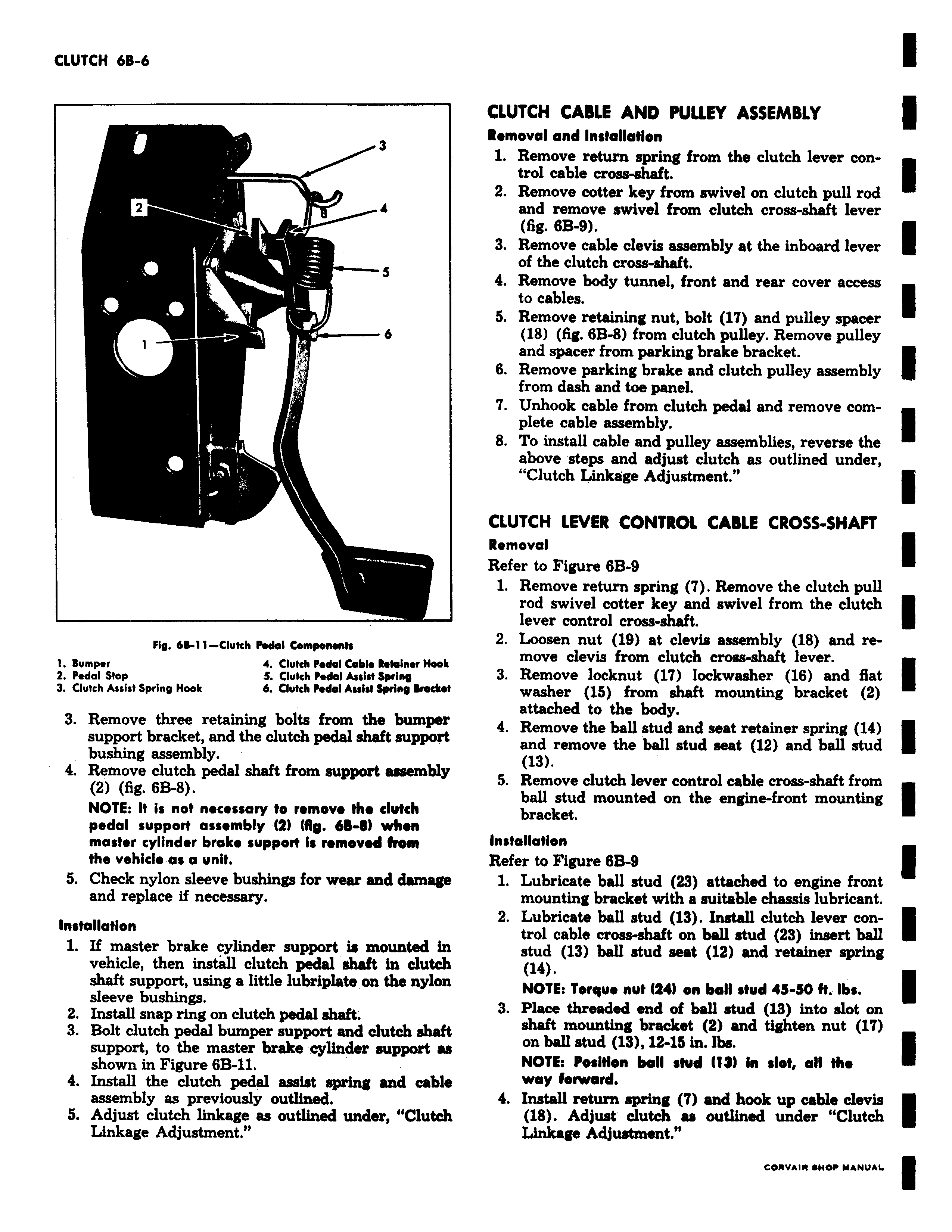
3 2 4 s 6 Fig 6d 11 Clutch Pedal Compenenh 1 Bumper 4 Clutch Pedal Cable Retainer Hook 2 Pedal Stop S Clutch Pedal Assist Spring 3 Clutch Assist Spring Hook 6 Clutch Pedal Assist Wnq Bracket 3 Remove three retaining bolts from the bumper support bracket and the clutch pedal shaft support bushing assembly 4 Remove clutch pedal shaft from support assembly 2 fig 6B 8 NOTE It is not necessary to remove the clutch pedal support assembly Z MS 6d 81 when master cylinder brake support is removed from the vehicle as a unit 5 Check nylon sleeve bushings for wear and damage and replace if necessary Installation 1 If master brake cylinder support is mounted in vehicle then install clutch pedal shaft in clutch shaft support using a little lubriplate on the nylon sleeve bushings 2 Install snap ring on clutch pedal shaft 3 Bolt clutch pedal bumper support and clutch shaft support to the master brake cylinder support as shown in Figure 6B 11 4 Install the clutch pedal assist spring and cable assembly as previously outlined 5 Adjust clutch linkage as outlined under Clutch Linkage Adjustment CLUTCH CABLE AND PULLEY ASSEMBLY Removal and Installation 1 Remove return spring from the clutch lever control cable cross shaft 2 Remove cotter key from swivel on clutch pull rod and remove swivel from clutch cross shaft lever fig 6B 9 3 Remove cable clevis assembly at the inboard lever of the clutch cross shaft 4 Remove body tunnel front and rear cover access to cables 5 Remove retaining nut bolt 17 and pulley spacer 18 fig 68 8 from clutch pulley Remove pulley and spacer from parking brake bracket 6 Remove parking brake and clutch pulley assembly from dash and toe panel 7 Unhook cable from clutch pedal and remove complete cable assembly 8 To install cable and pulley assemblies reverse the above steps and adjust clutch as outlined under Clutch Linkage Adjustment CLUTCH LEVER CONTROL CABLE CROSS SHAFT Removal Refer to Figure 6B 9 1 Remove return spring 7 Remove the clutch pull rod swivel cotter key and swivel from the clutch lever control cross shaft 2 Loosen nut 19 at clevis assembly 18 and remove clevis from clutch cross shaft lever 3 Remove locknut 17 lockwasher 16 and flat washer 15 from shaft mounting bracket 2 attached to the body 4 Remove the ball stud and seat retainer spring 14 and remove the ball stud seat 12 and ball stud 13 5 Remove clutch lever control cable cross shaft from ball stud mounted on the engine front mounting bracket Installation Refer to Figure 68 9 1 Lubricate ball stud 23 attached to engine front mounting bracket with a suitable chassis lubricant 2 Lubricate ball stud 13 Install clutch lever control cable cross shaft on ball stud 23 insert ball stud 13 ball stud seat 12 and retainer spring 14 NOTE Torque nut Z4 on ball stud 4S S0 N Ibs 3 Place threaded end of ball stud 18 into slot on shaft mounting bracket 2 and tighten nut 17 on ball stud 13 12 15 in lbs NOTE Position ball stud fl3l in slot all the way forward 4 Install return spring 7 and hook up cable clevis 18 Adjust clutch as outlined under Clutch Linkage Adjustment