Jeep Parts Wiki | Ford Parts Wiki
Home | Search | Browse
Prev

 Next
Next
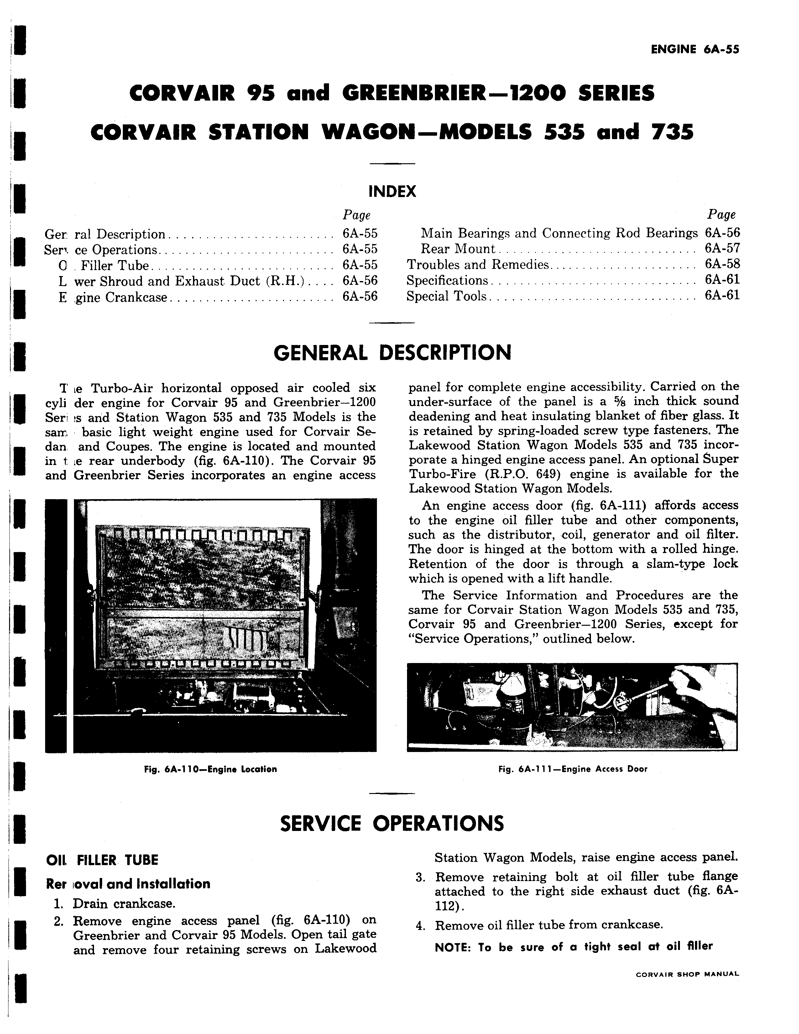
CORVAIR 95 and GRI CORVAIR STATION WAGI Ir Page Ger ral Description 6A 55 Seri ce Operations 6A 55 0 Filler Tube 6A 55 L wer Shroud and Exhaust Duct R H 6A 56 E gine Crankcase 6A 56 GENERAL Z te Turbo Air horizontal opposed air cooled six cyli der engine for Corvair 95 and Greenbrier 1200 Seri s arid Station Wagon 535 and 735 Models is the sarr basic light weight engine used for Corvair Sedan and Coupes The engine is located and mounted in 1 ie rear underbody fig 6A 110 The Corvair 95 and Greenbrier Series incorporates an engine access r 1 Fig 6A 110 Engine Location SERVICE C OII FILLER TUBE Rer ioval and Installation 1 Drain crankcase 2 Remove engine access panel fig 6A 110 on Greenbrier and Corvair 95 Models Open tail gate and remove four retaining screws on Lakewood ENBRIER 1Z00 SERIES ON MODELS 535 and 735 IDEX Page Main Bearings and Connecting Rod Bearings 6A 56 Rear Mount 6A 57 Troubles and Remedies 6A 58 Specifications 6A 61 Special Tools 6A 61 DESCRIPTION panel for complete engine accessibility Carried on the under surface of the panel is a 5 s inch thick sound deadening and heat insulating blanket of fiber glass It is retained by spring loaded screw type fasteners The Lakewood Station Wagon Models 535 and 735 incorporate a hinged engine access panel An optional Super Turbo Fire R P O 649 engine is available for the Lakewood Station Wagon Models An engine access door fig 6A 111 affords access to the engine oil filler tube and other components such as the distributor coil generator and oil filter The door is hinged at the bottom with a rolled hinge Retention of the door is through a slam type lock which is opened with a lift handle The Service Information and Procedures are the same for Corvair Station Wagon Models 535 and 735 Corvair 95 and Greenbrier 1200 Series except for Service Operations outlined below W Fig 6A 111 Engine Access Door PERATIONS Station Wagon Models raise engine access panel 3 Remove retaining bolt at oil filler tube flange attached to the right side exhaust duct fig 6A112 4 Remove oil filler tube from crankcase NOTE To be sure of a tight seal at oil filler e e e e u

 Next
Next