Jeep Parts Wiki | Ford Parts Wiki
Home | Search | Browse
Prev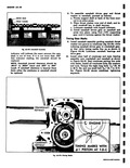
 Next
Next
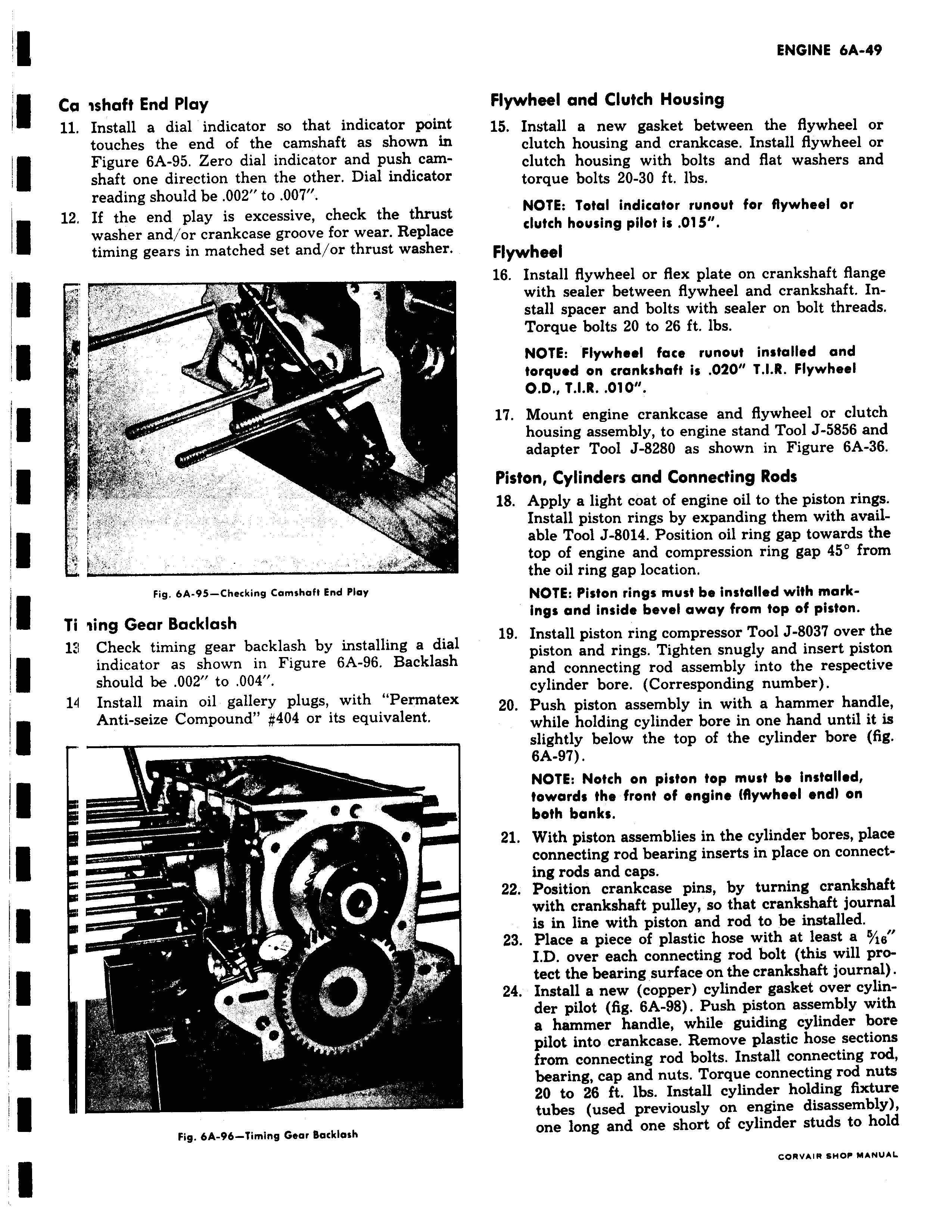
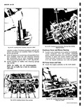
CA ishaft End Play 11 Install a dial indicator so that indicator poinl touches the end of the camshaft as shown u Figure 6A 95 Zero dial indicator and push cam shaft one direction then the other Dial indicatoi reading should be 002 to 007 12 If the end play is excessive check the thrusl washer and or crankcase groove for wear Replace timing gears in matched set and or thrust washer r s r Fig 6A 95 Checking Camshaft End Play Ti iing Gear Backlash 1 1 Check timing gear backlash by installing a dia indicator as shown in Figure 6A 96 Backlasl should be 002 to 004 19 Install main oil gallery plugs with Permate3 Anti seize Compound 404 or its equivalent P r s Fig 6A 96 Timing Gear Backlash Flywheel and Clutch Housing 15 Install a new gasket between the flywheel or clutch housing and crankcase Install flywheel or clutch housing with bolts and flat washers and torque bolts 20 30 ft lbs NOTE Total indicator runout for flywheel or clutch housing pilot is 015 Flywheel 16 Install flywheel or flex plate on crankshaft flange with sealer between flywheel and crankshaft Install spacer and bolts with sealer on bolt threads Torque bolts 20 to 26 ft lbs NOTE Flywheel face runout installed and torqued on crankshaft is 020 T LR Flywheel O D T LR 010 17 Mount engine crankcase and flywheel or clutch housing assembly to engine stand Tool J 5856 and adapter Tool J 8280 as shown in Figure 6A 36 Piston Cylinders and Connecting Rods 18 Apply a light coat of engine oil to the piston rings Install piston rings by expanding them with available Tool J 8014 Position oil ring gap towards the top of engine and compression ring gap 45 from the oil ring gap location NOTE Piston rings must be installed with markings and inside bevel away from top of piston I 19 Install piston ring compressor Tool J 8037 over the piston and rings Tighten snugly and insert piston and connecting rod assembly into the respective cylinder bore Corresponding number 20 Push piston assembly in with a hammer handle while holding cylinder bore in one hand until it is slightly below the top of the cylinder bore fig 6A 97 NOTE Notch on piston top must be installed toward the front of engine flywheel end on both banks 21 With piston assemblies in the cylinder bores place connecting rod bearing inserts in place on connecting rods and caps 22 Position crankcase pins by turning crankshaft with crankshaft pulley so that crankshaft journal is in line with piston and rod to be installed 23 Place a piece of plastic hose with at least a g LD over each connecting rod bolt this will protect the bearing surface on the crankshaft journal 24 Install a new copper cylinder gasket over cylinder pilot fig 6A 98 Push piston assembly with a hammer handle while guiding cylinder bore pilot into crankcase Remove plastic hose sections from connecting rod bolts Install connecting rod bearing cap and nuts Torque connecting rod nuts 20 to 26 ft lbs Install cylinder holding fixture tubes used previously on engine disassembly one long and one short of cylinder studs to holc t nev IR CROP MANUAL