Jeep Parts Wiki | Ford Parts Wiki
Home | Search | Browse
Prev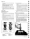
 Next
Next
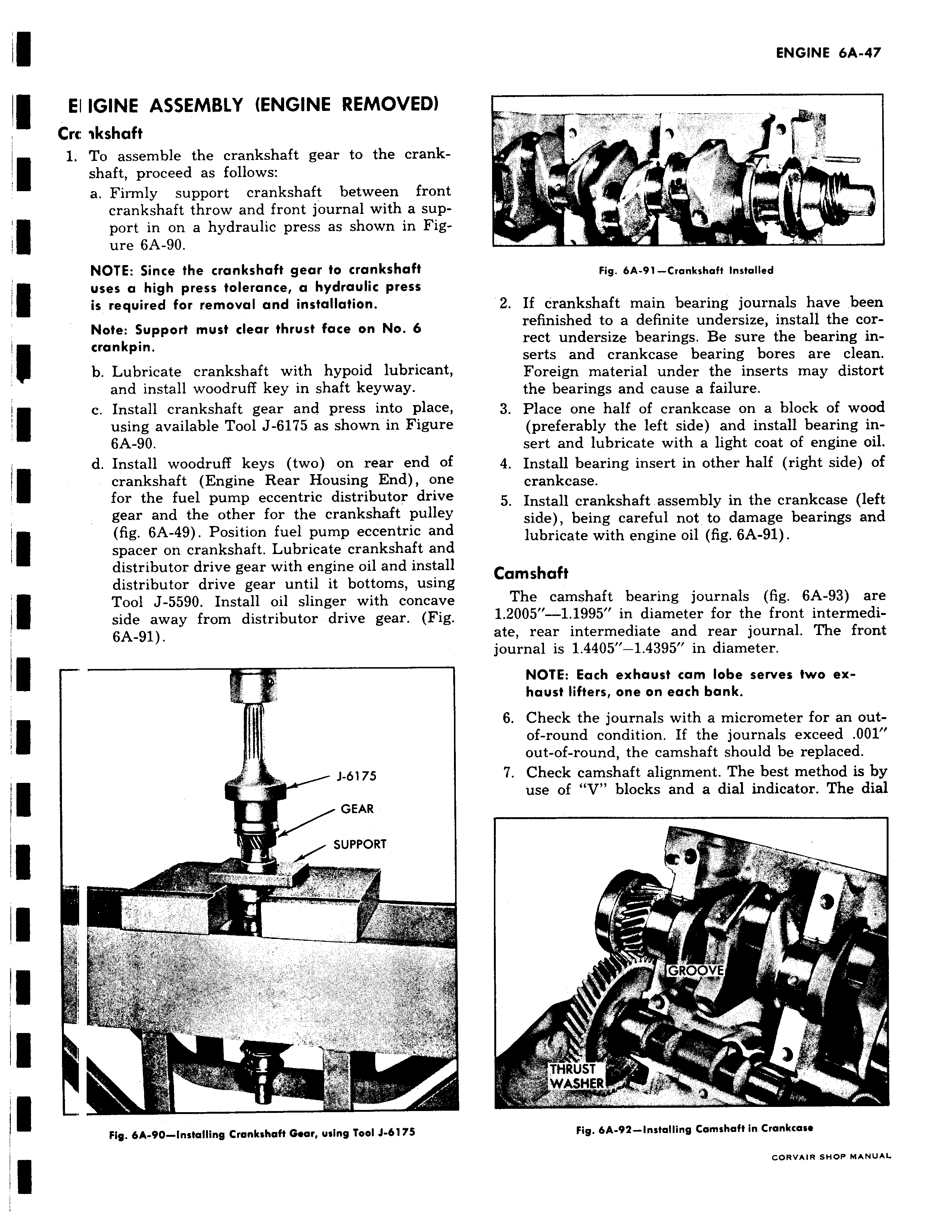
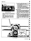
El IGINE ASSEMBLY ENGINE REMOVED Crc ikshaft 1 To assemble the crankshaft gear to the crank shaft proceed as follows a Firmly support crankshaft between front crankshaft throw and front journal with a support in on a hydraulic press as shown in Figure 6A 90 NOTE Since the crankshaft gear to crankshaft uses a high press tolerance a hydraulic press is required for removal and installation Note Support must clear thrust face on No 6 crankpin b Lubricate crankshaft with hypoid lubricant and install woodruff key in shaft keyway I c Install crankshaft gear and press into place ff using available Tool J 6175 as shown in Figure 6A 90 d Install woodruff keys two on rear end of I crankshaft Engine Rear Housing End one for the fuel pump eccentric distributor drive gear and the other for the crankshaft pulley fig 6A 49 Position fuel pump eccentric and spacer on crankshaft Lubricate crankshaft and distributor drive gear with engine oil and install distributor drive gear until it bottoms using Tool J 5590 Install oil slinger with concave side away from distributor drive gear Fig 6A 91 J 6175 GEAR SUPPORT wW 11 7 r a Fig 6A 90 Installing Crankshaft Gear using Tool J 6175 1 T Fig 6A 91 Crankshaft Installed 2 If crankshaft main bearing journals have been refinished to a definite undersize install the correct undersize bearings Be sure the bearing inserts and crankcase bearing bores are clean Foreign material under the inserts may distort the bearings and cause a failure 3 Place one half of crankcase on a block of wood preferably the left side and install bearing insert and lubricate with a light coat of engine oil 4 Install bearing insert in other half right side of crankcase 5 Install crankshaft assembly in the crankcase left side being careful not to damage bearings and lubricate with engine oil fig 6A 91 Camshaft The camshaft bearing journals fig 6A 93 are 1 2005 1 1995 in diameter for the front intermediate rear intermediate and rear journal The front journal is 1 4405 1 4395 in diameter NOTE Each exhaust cam lobe serves two exhaust lifters one on each bank 6 Check the journals with a micrometer for an outof round condition If the journals exceed 001 j out of round the camshaft should be replaced 7 Check camshaft alignment The best method is by use of V blocks and a dial indicator The dial r f s GROOvE THRUST r WASHER Fig 6A 92 Installing Camshaft in Crankcase GORVAIR SHOP MANUAL